
Owner's manual


CeilingVIEW HD HideAway Manual
CeilingVIEW HD HideAway Manual, Document Number 342-0289 Rev. B Page 6 of 24
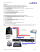
Dip Switch Settings:
Set the dip switches to the desired settings and then apply power to the system. To make any changes, remove
power from the system, make the change and re-apply power to the system.
Description / Dip Switch 1 2 3 4 5 6
CeilingVIEW HD HideAway IR Settings:
CeilingVIEW HD HideAway Camera 1 IR Frequency Setting R** R** * * * *
CeilingVIEW HD HideAway Camera 2 IR Frequency Setting L** R** * * * *
CeilingVIEW HD HideAway Camera 3 IR Frequency Setting R** L** * * * *
Vaddio ClearVIEW HD-20 Camera IR Settings: 1 2 3 4 5 6
Vaddio ClearVIEW HD-20 IR 1 Setting UP UP UP UP*** * *
Vaddio ClearVIEW HD-20 IR 2 Setting UP DN UP UP*** * *
Vaddio ClearVIEW HD-20 IR 3 Setting UP UP DN UP*** * *
Vaddio ClearVIEW HD-18/HD-19-18/HD-19 1 2 3 4 5 6
Vaddio ClearVIEW HD-18 and HD-19 IR 1 Setting UP UP UP*** * * *
Vaddio ClearVIEW HD-18 and HD-19 IR 2 Setting DN UP UP*** * * *
Vaddio ClearVIEW HD-18 and HD-19 IR 3 Setting DN DN UP*** * * *
* Position not applicable - currently dip switches marked * are in reserve for future use, please leave UP or R at this time.
**CeilingVIEW HD HideAway IR Settings: The dip switches are vertically mounted on the Main Circuit Board (PCBA). The
switches are set to the Right or Left (see Figure 3).
***IR OUT OFF: This dip switch is UP when using the Vaddio IR Remote Commander. This switch should be down if IR Forwarding
is used or if the Vaddio IR Remote Commander will not be used. Note: If the dip switch is set to DN it will disable the IR receiver in
the Vaddio Camera. The Vaddio Camera will not respond to the Vaddio IR Remote Commander.
STEP 2: Assembly and Installation Instructions for Suspended Acoustic Tile Ceilings:
A. Determine the desired location, distance and centering of the camera for your installation.
B. Check above the ceiling where you plan to install the motorized lift system and verify that the area is clear of
obstructions and confirm that there is adequate room for the motorized lift system enclosure. Verify that
you have proper building structure to attach the required support cables for the enclosure.
C. Remove the suspended ceiling tile that is to be used to install the CeilingVIEW HD HideAway from the ceiling
grid.
D. Place the suspended ceiling tile on a suitable and safe work surface.
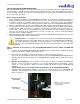
E. Position the Ceiling Tile Brace on the top of the suspended ceiling tile to be used for installation. The Ceiling
Tile Brace can be located in most any place (horizontally on the tile) from one end of the ceiling tile to the
opposite end; it does not have to be centered in the middle of the tile. However, verify that the Ceiling Trim Ring
will fit within the surface of the tile and not cover the suspended ceiling grid.
Note: The Ceiling Tile Brace is designed to lie across the tile in a 2 ft. direction only.
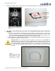
Figure 4: Ceiling Tile Brace on ceiling tile Figure 5: Outline of ceiling tile opening
Figure 6: Cut-out of ceiling tile opening Figure 7: Ceiling Tile Brace with opening
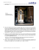
Warning: Do not install the CeilingVIEW HD HideAway in any suspended acoustic tile ceiling without support
cables! The support cables must be properly attached to the CeilingVIEW HD HideAway and to building
structure. Verif
y
y
our installation conforms to all applicable local buildin
g
codes with local officials!