
Manual


ClearVIEW HD-USB Conferencing Camera
ClearVIEW HD-USB PTZ Conferencing Camera Document Number 342-0437 Rev. D Page 7 of 36
Getting Started:
Step 1:
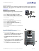
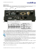
Using the HD Video Select Rotary Switch and Camera Settings Dip Switch on the back of the camera, set up
the camera’s output resolution and functional preferences. A reference label is on the bottom of the camera.
Switch Setting Label on Bottom of the HD-USB Camera:
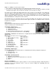
Step 2: For the best USB 2.0 video, set the HD VIDEO SELECT rotary switch to “0” (720p/59.94) on the HD-USB
Camera. All USB 2.0 UVC resolutions are derived from 720p/59.94. The USB 2.0 processor can accept rotary
positions 0 through 6, but please be aware that if 1080p/30 is scaled down to 320 x 180, well let’s just say…the
image will look much better if the PC scales from 720p than from 1080p (see note below).
Important Note: When using 1080p as the input, very low USB 2.0 resolutions such as 352 x 240 and 320 x 180 will either not
look so good, won’t work or the user may wish they didn’t work, due to how far the signal is scaled (squeezed/smashed/crushed)
down by the PC from the original input. Please use 720p or position “0” for the lower resolutions. Always start from a HD
resolution closest to what the UC client wants to use, send and display. In some cases the sharpness control can clean up the
image (both sharpen or smooth out the jaggies) if the native resolution of the application is too low.
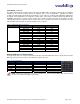
For concurrent USB 2.0 and Analog Component (YPbPr), switch settings 0 through 6 are the resolutions that
can be both digital (USB 2.0 or H.264) and Analog (YPbPr). These resolutions are the most used resolutions
for HD video in both HD videoconferencing and broadcast.
For Analog (YPbPr) output, all of the HD VIDEO SELECT switch settings will operate.
The Composite output on the BNC connector is independent from the USB 2.0 / IP resolutions. The SD
settings and are formatted by dip switches 5, 6 and 7.
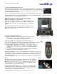
Step 3: Choose the IR frequency (1, 2 or 3) on the camera for use with the IR Remote Commander. Since only
one USB camera can be plugged into a PC at a time, recommended default is Freq. 1 (dip switches 1 & 2 up).
Step 4: Leave the IR out OFF (up) as default.
HD Video
Select Switch
Camera Settings 10-Position Dip Switches
HD-USB
Rear Panel
IR 1
1 & 2 UP
ON
SD
NTSC
SD
PAL
SD 4:3
6 & 7 UP
SD
LB
IMAGE
FLIP
OFF
ON ON
DIP SWITCH SETTINGS
8
12
3
4
567 910
HD VIDEO AND USB 2.0 SELECT
720p/59.94 - USB
1080i/59.94
0
1
2
3
4
5
6
7
8
9
A
B
C
D
E
F
1080p/59.94
1080p/60
720p/50
1080i/50
1080p/50
21
5
4
3768109
ON
IR 2
ON
IR 3
ON
IR
OUT
OFF
9600
bps
38400
bps
SD
SQ
TEST
BARS
OFF
10
OFF
480i/29.97
1080p/25
1080p/30
576i/25
USE ROTARY SETTINGS 0 through 6 FOR USB 2.0 OUT
SCALER