
Manual


CoverVIEW Installation and User Guide, Document 341-465 RevA, Page 2 of 4
INSTALLATION INSTRUCTIONS (continued)
Camera Backbox Installation
1. With the supplied mounting template measure and mark the rough wall opening and verify that the
template is level. Verify positioning of camera before cutting the drywall.
2. Carefully cut the opening in the drywall (or direct qualified drywall installer to cut the opening).
3. Carefully slide the camera backbox into the wall opening, and with mounting flanges against the wall,
mark the four mounting screw locations while leveling the backbox.
4. Carefully remove camera backbox from hole and drill the four 5/8” holes marked on the template.**
5. Route the cabling for the PTZ camera into the wall opening and determine which one of the three conduit
knockouts to use on the sides or top of the backbox and remove it.
6. Place the camera assembly in the backbox over the slot in the bottom of the box. Using the ¼”-20 x ¼”
screw, attach the camera assembly to the backbox. Gently slide camera assembly as far back into the
backbox as possible and then tighten the screw securely.
7. Using the four (4) - 1/4” x 2” long supplied screws and toggles, insert the screws through the front of the
mounting holes on the mounting flanges and secure toggles to the rear turning two or three turns.
8. Carefully insert backbox into mounting hole pressing the toggles completely into the wall.
9. Tighten the four mounting screws securely while checking the backbox for level.
**Alternate Installation Note: Standard EzAnchors® or spiral type drywall anchors can be used instead
of the toggle bolts if preferred. EzAnchors and screws are not included.
Bezel Installation
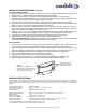
1. The acrylic lens is attached to the bezel at the factory and the protective film is scored to help with
removal. Taking care to avoid scratching the acrylic lens, peel off the protective film (Figure 2).
2. Center the bezel mounting template over the installed camera backbox. NOTE: Be sure to position the
TOP of the template over the TOP of the backbox and center the bezel to cover the entire backbox.
3. Check the template and make sure the template is level, then mark the four mounting holes.
4. Remove the template and drill four (4) - 3/16” holes as marked.
5. Carefully tap the four conical anchors into the wall until fully seated.
6. Install the bezel using the four (4) - 1” long sheet metal screws supplied in the hardware bag.
7. Snap trim panels into place on either side of the bezel, tabs inward toward the middle.
GENERAL SPECIFICTIONS
The CoverVIEW Cover is available for the Sony EVI-D100 and the Canon VC-C50i PTZ Cameras. Listed below are the specifications
for each product. Vaddio WallVIEW 100 PTZ and WallVIEW 50i PTZ kits using the Vaddio EZCamera Cabling System (EZCamera
Cabling Shoe, Quick-Connect Box for video power and control over Cat. 5 cabling) are also sized to fit perfectly in the CoverVIEW
backbox.
Cover/Enclosure Materials ABS/Acrylic Plastics
Cover/Enclosure Dimensions Depth – 4”; Width – 14 1/4”; Height – 8 1/2”
Cover/Enclosure Weight 8oz
Backbox Materials Painted Metal (black paint only)
Backbox Dimensions Sony: Depth – 4”/10.16cm; Width – 6 1/4”/15.88cm; Height – 6 1/4”/15.88cm
Backbox Dimensions Canon: Depth – 4”/10.16cm; Width – 6 1/4”/15.88; Height – 5 5/8”/16.83cm
Backbox Weight 1lb
Backbox Cutout Sony: 6 3/8”/16.19cm x 6 3/8”16.19cm
Backbox Cutout Canon: 6 3/8”/16.19cm x 5 3/4”/14.6cm
Backbox Install Hardware (4) Bolts and Toggles; (1) Seal-tight Cable Grommet, 1-1/4”-20 x ½” screw
Bezel Install Hardware (4) Conical wall anchors and (4) 1” sheet metal screws
*CoverVIEW Enclosures for Sony EVI-D100 is available in black or white.
**CoverVIEW Enclosures for Canon VC-C50i is available in black only.
Figure 2:
Back of bezel – Peel back the
protective film, carefully, taking care to
avoid scratching the acrylic lens. The
film is scored for easy removal.
Protective film is scored
top and bottom on front
and back of acrylic lens.