
Owner's manual


Vaddio DomeVIEW Indoor Pendant Mount Dome Installation and User Guide - Document 341-444 Rev. C
Page 11 of 12
Appendix 1:
Vaddio Power, Video and Control Pin-outs
For Vaddio DomeVIEW 70 and 50iR
Power/Video Connection RJ-45 – Camera Shoe
# Pins
1) Power (+)
2) Power GND
3) Video GND
4) Y (luminance)
5) Video GND
6) C (Chrominance)
7) Video GND
8) Composite Video
RS-232 Connector IN – Camera Shoe
# Pins
1) DTR (Sony® Daisy chain to DSR)
2) DSR (Sony Daisy chain from DTR)
3) CTS (Canon® Daisy chain to RTS)
4) RTS (Canon Daisy chain from CTS)
5) Unused
6) Digital GND
7) RXD (from TXD of control source)
8) TXD (to RXD of control source)
RS-232 Connector Out – Camera Shoe
# Pins
1) DSR (Sony Daisy chain from DTR)
2) DTR (Sony Daisy chain to DSR)
3) RTS (Canon Daisy chain from CTS)
4) CTS (Canon Daisy chain to RTS)
5) Unused
6) Digital GND
7) TXD (to RXD of control source)
8) RXD (from TXD of control source)
Power/Video Connection – RJ-45 – Quick-Connect Box
# Pins
1) Power +
2) Power GND
3) Video GND
4) Y (luminance)
5) Video GND
6) C (Chrominance)
7) Video GND
8) Composite Video
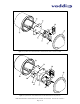
Power
Video
Power/Video Connector
Power/Video
Connector
RS-232 IN
RS-232 OUT
RS-232 IN
Vaddio Camera Shoe
Back View
Top
View
Vaddio Camera Shoe
Back View
RS-232 OUT
12345678
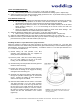
Vaddio Camera Shoe
Back View
RS-232
In
12345678
12345678
RS-232
Out
Top
View
RJ-45
Power/Video
Connector to
Camera Shoe
S-Video
From
Camera
Composite
Video From
Camera
Power Supply
To Camera Shoe
12345678
Power
Video