Installation and User Guide Camera and Electronic Products for Integrators VADDIO™ PRODUCTIONVIEW™ HD Camera Control Console with HD/SD Video Switching, Video Transitions, Up/Down Converting of Inputs and Outputs, Lower Screen Graphics and Automated Control Functionality Model Number 999-5600-000 (NTSC) Model Number 999-5600-001 (PAL) ©2009 Vaddio - All Rights Reserved. ProductionVIEW HD - Document Number 341-759 Rev.
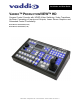
ProductionVIEW HD ProductionVIEW HD Overview The ProductionVIEW HD (Figure 1) incorporates seamless video switching, camera preset control and joystick camera control functionality into one of the most fully featured video consoles on the market today.
ProductionVIEW HD Key Technical Features: • Camera Auto-Sensing - The ProductionVIEW HD is capable of auto-sensing each PTZ camera attached.
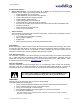
ProductionVIEW HD ProductionVIEW HD (Figure 2): 10 9 8 1 2 3 4 5 6 7 1. Focus and Iris Controls: Focus and Iris can be adjusted from knobs on the console for real-time control of these critical functions, when their respective Auto buttons are turned off. Auto White Balance (AWB) and Backlight Compensation (BLC) functions are available for compatible cameras. 2. Single Bus or Dual Bus Switching: ProductionVIEW HD can be configured as Program and Preview buses or as discrete video outputs (i.e.
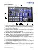
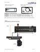
ProductionVIEW HD ProductionVIEW HD Back Panel I/O and Controls (Figure 3): 18 11 17 12 16 13 14 15 11. Power Input - Note: Use only the 18 VDC, 2.75A power supply provided with the ProductionVIEW HD. 12. Camera Control Ports on RJ-45 connectors: One camera control port per camera (no daisychaining required). Compatible with Sony, Canon and Vaddio PTZ cameras. See page 3 for details on cameras and camera systems compatible with ProductionVIEW HD. 13.
ProductionVIEW HD First Time Set-up with the ProductionVIEW HD: ProductionVIEW HD was designed to be exceptionally easy to use and operate right out of the box. All of the Vaddio standards for using video, power and control over Cat. 5 cabling are well documented and are in the manual and available free of charge from the Vaddio website. Getting Started: Connect all of the cameras, monitors and peripheral devices to ProductionVIEW HD.
ProductionVIEW HD Figure 5: Optional HD Accessory Cable (3 or 6 foot length) Figure 4: Optional SD Accessory Cable (Y-C & Composite) Vaddio Accessory Cable Part Numbers 440-5600-000 – 15-pin to SD (Y-C / CVBS) breakout cable (female BNCs – 1 foot) 440-5600-001 – 15-pin to HD Component (YPbPr/RGBHV) breakout cable (male BNCs – 3 foot) 440-5600-002 – 15-pin to HD Component (YPbPr/RGBHV) breakout cable (male BNCs – 6 foot) 440-5600-003 – 15-pin to HD Component (YPbPr/RGBHV) breakout cable (female BNCs – 7 i
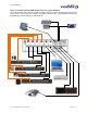
ProductionVIEW HD Figure 7: In-depth ProductionVIEW HD Camera Control System Examples The ProductionVIEW HD is ideal for controlling multiple cameras or more complicated systems (external control system, SD and HD PTZ cameras, a computer and DVD player, with StepVIEW mats and an AutoVIEW IR as external triggers) as outlined above. ProductionVIEW HD Manual 341-759 Rev.
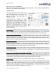
ProductionVIEW HD Operating the ProductionVIEW HD: Most of the console functions and controls are easy and intuitive. Over the next few pages there are details on how the different functions operate. Camera Controls The controls that can be used to adjust a PTZ camera are highlighted in the diagram to the right (mechanical functions are in gray, and electronic in blue). See notes below for additional information. ProductionVIEW HD is shipped with “Select Follow Preview” as the default setting.
ProductionVIEW HD Wipe, Dissolve or Cut To set up the switcher to transition from the current input selected as the Program output to another input, select a different video signal on the Preview bus. In the example to the right, Program is on Input 1 and Preview is on Input 3. Select the type of effect (wipe, cut or mix) that the switcher will use to transition from one input to the other.
ProductionVIEW HD Lower Screen Graphics Preparing to display Lower Screen Graphics on ProductionVIEW HD, first select your “background” video input (typically a live camera) on the Program bus, and then select the input that has the computer graphics that are to be displayed, on the Preview bus. In the example to the right, the background is Input 1 on Program, and the computer is on Input 6. To initiate the Lower Screen Graphic, press one of the LSG buttons on either bus, and the graphic will appear.
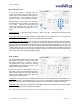
ProductionVIEW HD PIP Display To set up and display a Picture-In-Picture on the Program output, select the input that will be the “background” on the Program bus. Select the video input that will be the picture-in-picture, or in the “window” on the screen. In the example to the right, the background is Input 1 on the Program bus and Input 3 is the window on the Preview bus. Next, select the corner that the PIP window will show up in, using the P.I.P.
ProductionVIEW HD Master Power, Manual and Auto Modes (continued) Master Power Switch • When the Master Power Switch is powered down, all of the attached cameras will be placed in standby. Press and hold the power switch for 3 seconds to initiate power down sequence. This is a safeguard to prevent accidental shutdown. • When the Master Power Switch is powered up, all attached cameras will activate and select default camera and preset information as defined in the menu.
ProductionVIEW HD Video Input Menu >Select >All Ports (NOTE: Selecting ALL PORTS will configure all inputs to the same resolution) Ports 1 - 6 (NOTE: Same resolution options as Program Output menu, minus 1920 x 1200) Default Camera (Automatic and Start-up Modes – the default input selected on the Program bus when the system is turned on) >Select > 01 – 06 Selects inputs 1 through 6 as the default camera (default is 01) Default Preset (Automatic Mode – the default preset that the camera is sent to when the
ProductionVIEW HD Select Follow Preview >Select >On or Off When activated, camera selection switching follows the Preview bus selection, immediately transferring joystick and camera control directly to the camera selected on the Preview bus (On is default). NOTE: This function only works in Single Bus Mode – and not in Dual Bus Mode.
ProductionVIEW HD >Preset Location >Local >6 InCam 6 Local In “Local” mode, the ProductionVIEW stores all 12 presets internally In “6 InCam 6 Local” mode, the presets 1 through 6 will be stored in the cameras. Presets 7 through 12 will be stored in the ProductionVIEW. Note: The “6 InCam 6 Local” mode allows for switching video sources when cameras are moving to preset locations.
ProductionVIEW HD Compliance and CE Declaration of Conformity FCC Part 15 Compliance This equipment has been tested and found to comply with the limits for a Class A digital device, pursuant to Part 15 of the FCC Rules. These limits are designed to provide reasonable protection against harmful interference when the equipment is operated in a commercial environment.
ProductionVIEW HD Warranty Information: Hardware* Warranty - One year limited warranty on all parts. Vaddio warrants this product against defects in materials and workmanship for a period of one year from the day of purchase from Vaddio. If Vaddio receives notice of such defects during the warranty period, they will, at their option, repair or replace products that prove to be defective.
ProductionVIEW HD ProductionVIEW HD Back Panel (Figure 8): Connectors: Power: 18 VDC, 2.75A (5.5mm OD x 2.
ProductionVIEW HD General Specifications: Input Video Resolutions HD Resolutions: 1080i 59.94 1080i 50 720p 59.94 720p 50 1080p 59.94 * 1080p 50 * SD Resolutions: 480i NTSC - Composite or Y/C 576i PAL - Composite or Y/C RGBHV Resolutions**: 640 x 480 @ 60Hz - VGA 640 x 480 @ 75Hz - VGA 800 x 600 @ 60Hz - SVGA 1024 x 768 @ 60Hz - XGA 1024 x 768 @ 75Hz - XGA 1280 x 768 @ 60Hz 1280 x 1024 @ 60Hz - SXGA 1366 x 768 @ 60Hz - WXGA 1400 x 1050 @ 60Hz - SXGA+ 1600 x 1200 @ 60Hz - UXGA H. Freq (kHz) 31.5 37.5 37.
ProductionVIEW HD Appendix 1: RS-232 Control The ProductionVIEW HD has six (6) discrete camera control ports which eliminates the need for daisychaining control cabling. With ProductionVIEW HD, all cabling configurations are home-run wiring configurations. Each Channel will auto-configure the input channel for control of the camera attached. Vaddio uses simple control protocols to accomplish custom programming with the ProductionVIEW HD.
ProductionVIEW HD Appendix 1: Command Structure Definitions Command AWB BLC Camera CamFolPrv ClearAll Config Cut DefaultCam DspCams ExtTrigger Focus FTB Home IdleRtn Iris JPanDir JPanSpd JTiltDir JTiltSpd JZoomDir JZoomSpd lsgDen LSgSize Mix Move OnCamInit PanSpeed PipLoc Power Preset PresetLoc PrevIn ProgIn Rescan Reset ResetVideo Save Config SerialEcho SerialInfo SetDefault Store SwMode SysMode Take Tally TiltSpeed Version Wipe WipeSel Zoom ZoomSpeed Parameters AWB On/Off(cr) BLC On/Off(cr) Camera [9](c
ProductionVIEW HD Appendix 2: Video and Control Pin-out Table for ProductionVIEW HD Pin RGBHV YPbPr 1 Red Pr 2 Green Y 3 Blue Pb 4 ID - 5 N/C - 6 Red GND Pr GND 7 Green GND Y GND 8 Blue GND Pb GND Y/C & Composite Adapter Cable 9 No Pin - 10 GND - GND 11 ID - Y - Luminance 12 ID - C - Chrominance 13 H-Sync - 14 V-Sync - 15 N/C - Composite Camera Control Ports 1 through 6 - RS-232 on RJ-45 Connectors: PIN# 1) 2) 3) 4) 5) 6) 7) 8) Signal Unused Unused Unus
ProductionVIEW HD 9433 Science Center Drive, Minneapolis, MN 55428 Toll Free: 800-572-2011 ▪ Phone: 763-971-4400 ▪ FAX: 763-971-4464 www.vaddio.com ©2009 Vaddio - All Rights Reserved. Reproduction in whole or in part without written permission is prohibited. Specifications and pricing are subject to change without notice. Vaddio, ProductionVIEW, TouchVIEW, Quick-Connect, StepVIEW, AutoVIEW, CeilingVIEW, WallVIEW, EZCamera, MicVIEW and PowerRite are registered trademarks of Vaddio.