
User guide


ProductionVIEW HD
ProductionVIEW HD Manual 341-759 Rev. C Page 5 of 24
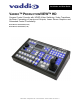
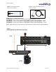
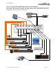
ProductionVIEW HD Back Panel I/O and Controls (Figure 3):
11. Power Input - Note: Use only the 18 VDC, 2.75A power supply provided with the ProductionVIEW
HD.
12. Camera Control Ports on RJ-45 connectors: One camera control port per camera (no daisy-
chaining required). Compatible with Sony, Canon and Vaddio PTZ cameras. See page 3 for details
on cameras and camera systems compatible with ProductionVIEW HD.
13. Video Inputs: Each input will accept either an SD (composite or Y-C), HD (Y, Pb, Pr) or RGBHV
video signals (selectable via internal menu) on the VGA connector. See the Video Resolutions table
on page 20 for all signals and resolutions supported.
14. Preview Outputs – Delivers the same SD (composite or Y-C), HD (Y, Pb, Pr) or RGBHV signal
(selectable via internal menu) on both VGA connectors. See the Video Resolutions table on page 20
for all signals and resolutions supported.
15. Program Outputs – Delivers the same SD (composite or Y-C), HD (Y, Pb, Pr) or RGBHV signal
(selectable via internal menu) on both VGA connectors. See the Video Resolutions table on page 20
for all signals and resolutions supported.
16. Tally Outputs – Allows for connecting ProductionVIEW HD to external Tally inputs such as PreVIEW
HD monitors, Quick-Connect CCU and other third-party tally sources.
17. Input Triggers for use in Automatic mode - Input Triggers for input channels 1 and 2. Configurable
in two modes (6 triggers for Input 1 and 6 triggers for Input 2, or 12 triggers for input 1 only).
Supports Vaddio AutoVIEW IR, StepVIEW, TouchVIEW and MicVIEW trigger inputs.
18. Control Port Input - DB-9 for RS-232 control of internal functions (Pin 2 = TX, Pin 3 = RX, Pin 5 =
GND).
Vaddio accessory cables for SD (Y-C or composite) and HD component (YPbPr) are sold separately.
11
12
13 14
15
16
17
18