
User guide


WallVIEW DVI/HDMI HD-20
WallVIEW DVI/HDMI HD-20 Manual 342-0180 Rev. D Page 9 of 20
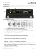
System Connectivity Example 2: System connectivity of two (2) Vaddio HD-20 cameras and two (2) Quick-
Connect DVI/HDMI SR Interfaces configured with single control port codec and Daisy Chain Control Emulation
(DCCE).
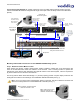
Mounting and Installation Instructions for the CONCEAL Wall Mounting System:
Step 1: Determine Camera Mount Location
When locating the camera, consider viewing angles, lighting conditions, possible line of site obstructions and
check for in-wall obstructions where the camera is to be mounted. Pick a mounting location to optimize the
performance of the camera. After determining the optimum location of the camera system, route the required two
(2) Cat-5e cables from the camera to the head-end.
The two (2) Cat-5e cables should feed-through a 1” (25.4mm) opening (circular or square shape) centered in the
rectangular slot located on the rear flange of the CONCEAL Wall Mount Bracket (see Fig. 1).
Note: Do not cut out the entire rectangular slot opening in the wall! This will not allow the two-lower wall
anchors to correctly fasten the Conceal Wall Mount to the wall (see Fig. 1).
Vaddio HD-20
HD Camera Systems
DVI to HDMI
Cable
IR
Daisy Chain Link between
Quick-Connect Interfaces
DVI Cable
Computer
with DVI
Output
C60 Codec
Microphones
ETHERNET
DVI Cable
Single RS-232 Port Codec with
Daisy Chain Camera Control
Codec IR Remote:
Forwarded through
Main Camera for
Codec Control
RS-232
RS-232
Two (2) - Cat-5e
Cables - up to
100’
(
30.48m
)
Power to Camera
HD Video from
Camera - Cat-5e
Power to Camera
HD Video from
Camera - Cat-5e
RS-232 & IR Return Cat-5e
Two (2) - Cat-5e
Cables - up to 100’
(
30.48m
)
RS-232 & IR Return Cat-5e
HD Video Monitors*
*Simulated Video Feeds
Monitor 1
Monitor 2
DVI-D
HDMI
Quick-Connect
DVI/HDMI SR
Interfaces
Fig. 2: Vaddio HD-20 Camera
aligned and attached to the
CONCEAL Wall Mount Bracket
Fig. 1: CONCEAL Wall Mount Bracket:
Cabled and Attached to Wall