Installation manual For the competent person Installation manual auroTHERM exclusive VTK 570/2; VTK 1140/2 GB, IE
Legal information Document type: Installation manual Product: Target group: auroTHERM exclusive – VTK 570/2 – VTK 1140/2 Authorised competent person Language: EN Document_number_version: 0020077994_02 Created on: 16.05.2012 Publisher/manufacturer Vaillant GmbH Berghauser Str. 40 D-42859 Remscheid Telefon +49 21 91 18‑0 Telefax +49 21 91 18‑28 10 info@vaillant.de www.vaillant.
Contents Contents 2.5 Regulations (directives, laws, standards) ............... 8 2.5.1 Installation regulations................................................ 8 1 Notes on the documentation .............................. 5 2.5.2 Regulations for the prevention of accidents ......... 8 1.1 Symbols used................................................................. 5 2.6 CE label............................................................................ 9 1.
Contents 5.2 Carrying out the installation .................................... 47 5.2.1 Installing racks ............................................................ 47 5.2.2 Installing collectors ..................................................... 51 5.2.3 Installing hydraulic connections ............................ 54 8 Decommissioning ................................................ 61 8.1 Temporary decommissioning ................................... 61 8.2 Permanently decommissioning .
Notes on the documentation 1 1 Notes on the documentation 1.1 Symbols used 1.3 Document handover ▶ Symbols The following symbols may appear: Document storage Pass this installation manual and all other applicable documents and, if necessary, any required tools to the system operator. Availability of documents Warning symbol (→ Page 6) The system operator is responsible for storing the documents so that they are available whenever required. Information symbol 1.
2 Safety 2 2.1 Safety Action-related warnings Classification of action-related warnings The action-related warnings are classified in accordance with the severity of the possible danger using the following warning signs and signal words: Warning symbols and signal words Danger! Imminent danger to life or risk of severe personal injury Danger! Risk of death from electric shock Warning. Risk of minor personal injury Caution. Risk of material or environmental damage 2.
Safety 2 2.3.6 Risk of death due to inadequate fastening of the collectors ▶ Collectors can fall from their anchors if they are not properly fastened on the roof. Collectors falling from the roof could cause life-threatening accidents. 2.3.12 Material damage due to an unsuitable tool ▶ ▶ ▶ ▶ ▶ Perform all work steps as described in this manual. Observe all safety precautions described in this manual. In addition, comply with all safety regulations that specifically apply in your region.
2 Safety 2.4 Intended use 2.5 Regulations (directives, laws, standards) 2.4.1 Intended use 2.5.1 Installation regulations Vaillant auroTHERM VTK tube collectors are used for solar heating support and for solar-supported hot water generation. Regulations Applies to: Great Britain Technical Guidance 2.4.2 Suitability of the equipment The collectors must only be operated with Vaillant readymixed solar fluid. Passing heating water or hot water directly through the collectors constitutes improper use.
Safety 2 injuries to person in or about the building as well as workers, passers by and the general public at large.
3 Description of the unit 3 Description of the unit 3.1 3.3 Purpose of the unit The collectors are used for solar heating support as well as for solar-supported hot water generation. Type overview – VTK 570/2 – VTK 1140/2 3.2 Information on the identification plate Information on the identification plate Meaning CE label: The collectors comply with the relevant product-specific European guidelines.
On-roof fitting and installation 4 4 ▶ On-roof fitting and installation When fitting and installing the collectors, you must observe the chapter "Safety". 4.1 Preparing for fitting and installation 4.1.1 Delivery, transport and positioning 4.1.1.1 Storing collectors ▶ To prevent moisture from penetrating into the collector, always store the collectors dry and in a weatherproof area.
4 On-roof fitting and installation 4.1.1.2 Checking the scope of delivery 12 1 11 2 10 9 8 7 3 4 6 List of materials for on-roof installation 1 VTK 1140/2 rail set 2 pc. 2 VTK 570/2 rail set 2 pc. 3 VTK 570/2 tube collector 1 pc. 4 VTK 1140/2 tube collector 1 pc. 5 VTK installation set (basic set) 1 pc. 6 VTK installation set (extension set) 1 pc. 7 Stop valve, 2-way VTK for parallel connection 1 pc. 12 5 8 9 10 Roof bracket type P (for pantile) (basic set) 4 pc.
On-roof fitting and installation 4 11 ▶ Hanger bolt fastening set (basic set) 4 pc. Hanger bolt fastening set (extension set, on top of each other) 2 pc. 12 Long base, hook type P 4 pc. Use the image to check that the installation sets are complete.
4 On-roof fitting and installation 4.1.1.3 Transporting collectors Conditions: Parallel connection, aperture surface area: ≤ 7 m² 1. To protect the collectors against damage, always transport them when they are standing horizontally. 2. Transport the collectors to the roof using suitable aids. 4.1.2 Complying with clearances and installation clearances In order to fit the collectors correctly, the specified clearances and installation clearances must be observed.
On-roof fitting and installation 4 Conditions: Parallel connection ▶ ▶ 3. Fix the roofing felt membrane tight to the roof batten, so that any moisture runs off to the side. To avoid pressure losses in the sub-collector fields, only use parallel connection for collector rows with the same number of collectors. Ensure that each sub-collector field has the same total tube length in the flow and return (Tichelmann system), in order to avoid pressure losses in the connection tubes. 4.1.
4 On-roof fitting and installation 4.1.5 Putting together components Note In the case of roof batten clearances greater than 460 mm, the 2-row and 3-row installations are not possible. In this case, you can install the 2 or 3 rows individually (without using the same central roof anchor). Conditions: Collector rows: 1 ▶ Use the following table to put together the components for installation.
On-roof fitting and installation 4 Number of VTK 1140/2 collectors 1 2 3 4 5 6 Number of VTK 570/2 collectors 1 1 1 1 1 1 Components 1 2 Required sets 1 set per row for connecting to the pipelines; the collectors are connected together using the extension set Valid up to 700 m above sea level Conditions: Collector rows: 2 A B A ▶ Use the following table to put together the components for installation.
4 On-roof fitting and installation Conditions: Collector rows: 3 A B B A ▶ Use the following table to put together the components for installation.
On-roof fitting and installation 4 4.1.6 1. Determining the number of required roof brackets ▶ b [m] Ask the local building authority for the regional maximum snow load sk. Conditions: Maximum snow load: ≤ 3 kN/m² ▶ The values for the edge clearances to be observed, eshort and elong can be found in the following tables. Install 4 roof brackets per collector. H [m] 5 6 7 8 9 10 8 1.0 9 1.0 11 11 1.0 1.1 ▶ 12 1.0 1.2 13 1.0 1.2 1.3 14 1.0 1.2 1.
4 On-roof fitting and installation nAdjacent array configuration 4.1.8.1 Specifications/technical data Pre-installation dimension (*) 4.1.8.2 A A = Finished installation dimension (**) + 2025 mm u Array configuration on top of each other Note In the case of roof batten clearances greater than 460 mm, the 2-row and 3-row installations are not possible. In this case, you can install the 2 or 3 rows individually (without using the same central roof anchor). C A B B B B D 1.
On-roof fitting and installation 4 Conditions: Collector rows: 2 Specifications/technical data Pre-installation dimension (*) = Finished installation dimension (**) + 2025 mm E E A A C B ▶ A E B B D B Define the clearances of the roof brackets.
4 On-roof fitting and installation Conditions: Collector rows: 3 Quantity VTK 570/2 E ▶ VTK 1140/2 A B C D ‑ 1 1397 ‑ 2 2794 ‑ 3 4191 ‑ 4 ‑ 5 ‑ 6 ‑ 7 1 1 1 2 1 3 1 4 6295 1 5 7692 1 6 8382 E 5588 1663 * / 1638 ** 100 200 VTK1140 997 1197 ‑‑‑‑‑ VTK570 507 607 6985 8382 9779 5006 2104 3501 4898 Ensure that there is sufficient play for the anchors.
On-roof fitting and installation 4 1. Use the top, middle and lower type P roof brackets shown. 3 4 A B ▶ 5 mm Undo the top bolt until the height of the roof bracket can be adjusted (3). Working materials 2 1 2. Secure the type P roof bracket either to the rafters (A) or to the roof batten (B). 3. To do this, loosen the bolt (1) on the base of the roof bracket with the enclosed bit and unscrew the bolt by approx. 5 mm. 4.
4 On-roof fitting and installation Conditions: Fastening type: To roof batten 2 A 5 6 3 1 ▶ ▶ ▶ ▶ Define the clearances of the roof brackets. (→ Page 20) Slide one to two pantiles upwards at the corresponding position above the roof batten (1). Undo the top bolt until the height of the roof bracket can be adjusted (2). Working materials Tighten the top bolt (5). Working materials SW 13 spanner ▶ ▶ Slide the pantiles into their original position again (6).
On-roof fitting and installation 4 4.2.1.4 Installing the hanger bolt type 3 4 1 2 4. Screw the roof bracket onto the roof batten or rafters using the three screws supplied (3). 5. Slide the pantiles into their original position again (4). 4.2.1.3 Installing type S flat (for slate) 1. Define the clearances of the roof brackets. (→ Page 20) 2. At the corresponding position, drill a hole in the pantile (1). 3. Tighten the hanger bolt onto the rafters through the pantile(2). 1 2 3 1.
4 On-roof fitting and installation 7. Disconnect the threaded rod directly above the nut (6). 8. Deburr the interface. Connecting mounting rails 4.2.2 Installing collectors Danger! Personal injury and material damage due to a falling collector. Improper fastening may cause a collector to fall. ▶ Tighten the clamping elements. ▶ Check for proper tensioning by shaking the clamping blocks. ▶ If a clamping block is mobile, tighten the nut again. 1.
On-roof fitting and installation 4 Laying and hooking collectors Removing the carrying strap 1 15. Remove the carrying strap. Danger! Risk of burns and scalding! Installing additional collectors In the event of solar radiation inside the units, collectors can reach 300 °C. ▶ Avoid working in direct sunlight. ▶ Cover the collectors before starting work. 1 ▶ You should preferably perform the work in the morning. ▶ Wear suitable safety gloves. 10.
4 On-roof fitting and installation 27. Tighten the clamping elements of the top mounting rails. Tightening the clamping ring connection Working materials SW 13 spanner Positioning the central mounting rail Conditions: Collector rows: 2 … 3 1 2 Caution. Risk of damage to the collectors as a result of improper installation. If the hydraulic connections are not installed properly, the stainless steel tubes inside the collector may become damaged.
On-roof fitting and installation 4 4.2.3 Installing hydraulic connections Installing the upper collectors Conditions: Collector rows: 2 … 3 1 3 Caution. Lack of tightness due to incorrect accessories. 2 Incorrect accessories may result in lack of tightness of the solar circuit and cause material damage.
4 On-roof fitting and installation Conditions: Collector rows: 2 … 3 ▶ ▶ ▶ ▶ ▶ Connect the collectors in accordance with the connection regulations (→ Page 14). Connect the collector flow and return to the system with the connection tubes. To do this, connect the clamping ring connection (from the installation set VTK basic set, article number 0020076776) to the collector. Connect the clamping ring connection with the connection pipework. Check the connections for tightness.
On-roof fitting and installation 4 4.3 Completing and checking the installation 4.3.1 Checking installation Use the following checklist to ensure that all work steps have been performed.
4 On-roof fitting and installation 4.3.2 Disposing of the packaging The transport packaging consists largely of recyclable materials. ▶ ▶ 32 Observe the applicable regulations. Dispose of the transport packaging properly.
Flat roof fitting and installation 5 5 ▶ Flat roof fitting and installation When fitting and installing the collectors, you must observe the chapter "Safety". 5.1 Preparing for fitting and installation 5.1.1 Delivery, transport and positioning 5.1.1.1 Storing collectors ▶ To prevent moisture from penetrating into the collector, always store the collectors dry and in a weatherproof area.
5 Flat roof fitting and installation 5.1.1.2 Checking the scope of delivery 1 10 2 9 3 8 4 5 6 7 List of materials for flat roof installation 1 VTK 1140/2 rail set 2 pc. 2 VTK 570/2 rail set 2 pc. 3 Frame set 1 pc. 4 Load plates from load plate set 4 pc. 5 Hammer-head bolt and nut from load plate set 2 pc. ▶ 6 7 8 9 10 VTK 570/2 tube collector 1 pc. VTK 1140/2 tube collector 1 pc. Stop valve, 2-way VTK for parallel connection 1 pc. VTK installation set (basic set) 1 pc.
Flat roof fitting and installation 5 5.1.1.3 Transporting collectors Conditions: Parallel connection, aperture surface area: ≤ 7 m² 1. To protect the collectors against damage, always transport them when they are standing horizontally. 2. Transport the collectors to the roof using suitable aids. 5.1.2 Complying with clearances and installation clearances During storms, strong wind forces occur along the edges of flat roofs.
5 Flat roof fitting and installation Conditions: Parallel connection 5.1.5 Selecting the installation variant C B A ▶ ▶ ▶ To avoid pressure losses in the sub-collector fields, only use parallel connection for collector rows with the same number of collectors. Ensure that each sub-collector field has the same total tube length in the flow and return (Tichelmann system), in order to avoid pressure losses in the connection tubes. 5.1.
Flat roof fitting and installation 5 5.1.6 ▶ Putting together components Use the following table to put together the components for installation.
GR AL MK ME BA IT SI AT > 108 km/h < 108 km/h < 99 km/h < 90 km/h < 81 km/h < 72 km/h PT ES IE IS AD GB FR BE NL CH LU DE DK NO CZ HR SE HU SK PL RS LT RO BG LV FI EE BY MD UA RU TR 5 Flat roof fitting and installation 5. Use the map to determine the basic wind speed at the site.
Flat roof fitting and installation 5 L2 L1 6. Use the tables to determine the required weights.
5 Flat roof fitting and installation Horizontal collector position Installation angle 45° Weights/rack [kg] To secure against sliding and lifting To secure only against lifting (if secured/anchored against sliding) Building height Building height L2 L1 Basic wind speed [km/h] 40 Position up to 10 m 10-18 m 18-25 m up to 10 m 18-25 m 18-25 m up to 72 Inland L₁ L₂ 299 213 372 274 421 314 30 191 30 242 30 276 up to 72 Coast and islands L₁ L₂ 406 301 476 359 521 396 30 265 30 315
Flat roof fitting and installation 5 Horizontal collector position Installation angle 60° Weights/rack [kg] To secure against sliding and lifting To secure only against lifting (if secured/anchored against sliding) Building height Building height L2 L1 Basic wind speed [km/h] Position up to 10 m 10-18 m 18-25 m up to 10 m 10-18 m 18-25 m up to 72 Inland L₁ L₂ 268 297 334 377 378 430 30 196 37 247 45 281 up to 72 Coast and islands L₁ L₂ 365 414 430 491 474 539 43 271 54 320 62
5 Flat roof fitting and installation Vertical collector position Installation angle 30° Weights/rack [kg] To secure against sliding and lifting To secure only against lifting (if secured/anchored against sliding) Building height Building height L2 L1 Basic wind speed [km/h] 42 Position up to 10 m 10-18 m 18-25 m up to 10 m 10-18 m 18-25 m up to 72 Inland L₁ L₂ 301 167 378 213 429 244 44 167 40 213 70 244 up to 72 Coast and islands L₁ L₂ 413 234 487 279 534 307 67 234 81 279
Flat roof fitting and installation 5 Vertical collector position Installation angle 45° Weights/rack [kg] To secure against sliding and lifting To secure only against lifting (if secured/anchored against sliding) Building height Building height L2 L1 Basic wind speed [km/h] Position up to 10 m 10-18 m 18-25 m up to 10 m 10-18 m 18-25 m up to 72 Inland L₁ L₂ 321 191 401 245 454 281 30 173 30 220 30 251 up to 72 Coast and islands L₁ L₂ 437 270 513 321 562 354 30 241 30 286 30 3
5 Flat roof fitting and installation Vertical collector position Installation angle 60° Weights/rack [kg] To secure against sliding and lifting To secure only against lifting (if secured/anchored against sliding) Building height Building height L2 L1 Basic wind speed [km/h] 44 Position up to 10 m 10-18 m 18-25 m up to 10 m 10-18 m 18-25 m up to 72 Inland L₁ L₂ 297 267 372 339 421 387 30 179 30 225 37 256 up to 72 Coast and islands L₁ L₂ 406 372 477 441 522 485 30 246 30 291
Flat roof fitting and installation 5 5.1.8 Defining the rack clearances B Conditions: Installed collectors: VTK 1140/2 C A F E C D ▶ Define the rack clearances.
5 Flat roof fitting and installation Quantity VTK 570/2 1) 46 30° VTK 1140/2 A 1 5 7364 1 6 8761 B 1106 45° F 1) 2420 B 1476 60° F 1) 3001 B 1749 F 1) 3267 C D E G 1684 543 1397 1233 Sun elevation of 20° (winter sun) Installation manual auroTHERM exclusive 0020077994_02
Flat roof fitting and installation 5 5.2 Carrying out the installation Specifications/technical data 5.2.1 Installing racks Installation angle – 30° – 45° – 60° Danger! Risk of death due to falling collectors! Unsecured collectors may fall from the flat roof due to the wind and present a danger to persons. 1 ▶ Perform the following safety precau- tions according to the installation type. ▶ For direct connection, screw the rack ▶ ▶ 1. properly onto the base. Only use suitable load weights.
5 Flat roof fitting and installation Conditions: Type of installation: Direct mounting Conditions: Type of installation: Floating installation (with load plates) Screwing on the rack Preparing load plates Caution. Lack of tightness due to destruction of the roof skin. In the event of destruction of the roof skin, water can penetrate the building. ▶ Check the tightness of the roof skin after tightening screw connections. ▶ Restore the tightness of the roof skin if necessary.
Flat roof fitting and installation 5 ▶ Align the load plates approximately in their final position on the flat roof. ▶ ▶ ▶ ▶ ▶ Insert the first hammer-head bolt centrally in the groove between the first two load plates. To secure the hammer-head bolt, turn it by 90° in a clockwise direction. Secure the second hammer-head bolt in the same way between the other two load plates. 3 Install the second rack on the load plates as described above.
5 Flat roof fitting and installation Placing load weights on load plates ▶ ▶ ▶ Transport the required number of loading weights to the flat roof. Place the load weights on the load plates as shown above. Ensure that the distance between the loading weights and the racks is as small as possible.
Flat roof fitting and installation 5 Sliding on mounting rails 1 2 3 Screwing the rack onto weights ▶ ▶ ▶ Take hold of the first rack that is already secured in the installation angle. Screw the front rack feet onto the first weight. Screw the rear rack feet onto the second weight. ◁ The first rack is installed so that it is stable. 2. Slide the two mounting rails (top and bottom) onto the brackets, as shown in the image. 3.
5 Flat roof fitting and installation Connecting mounting rails Hooking the collector in at the bottom 1 1 10. Clamp the rail connector (1) into the mounting rails. 11. Ensure that the rail connector (1) engages in the holes of the mounting rails. Danger! Risk of burns and scalding! In the event of solar radiation inside the units, collectors can reach 300 °C. Note After installation, the rail connectors are no longer accessible. ▶ Avoid working in direct sunlight.
Flat roof fitting and installation 5 Removing the carrying strap Fitting connectors A 18. Remove the carrying strap. 1 B 2 21. Screw the double nipple (A) (from installation set VTK extension set, article number 0020076779) in the thread of the second collector (B) with the cap nut of the first collector ((1) and (2)). 22. Push the collectors together. Loosening the sun protection film Tightening the clamping ring connection 1 19.
5 Flat roof fitting and installation 26. Remove the carrying strap. (→ Page 53) 27. Loosen the sun protection film from the edges of the collector. (→ Page 53) 2. To do this, connect the clamping ring connection (from the installation set VTK basic set, article number 0020076776) to the collector. Completing collector rows 3. Connect the clamping ring connection with the connection pipework. 4. Check the connections for tightness. Conditions: Not all collectors in a row have been installed yet.
Flat roof fitting and installation 5 5.3 Completing and checking the installation 5.3.1 Checking installation Use the following checklist to ensure that all work steps have been performed.
5 Flat roof fitting and installation 5.3.2 Disposing of the packaging The transport packaging consists largely of recyclable materials. ▶ ▶ Observe the applicable regulations. Dispose of the transport packaging properly.
Inspection and maintenance 6 6 6.1 Inspection and maintenance 6.3 Maintenance plan Danger! Risk of death, injury and material damage due to improper maintenance and repairs! The following table shows the inspection and maintenance work that must be carried out at specific intervals. 6.1.1 General inspection and maintenance instructions Improper maintenance work or repairs can impair the operating safety of the unit and result in material damage and personal injury.
6 Inspection and maintenance 6.5 Checking collectors and connections for damage, dirt and lack of tightness 1. Check the collectors for damage. If the collectors are damaged: ▶ Replace the collectors. 2. Check the collectors for dirt. If the collectors are dirty: ▶ Clean the collectors. (→ Page 58) 3. Check the connections for lack of tightness. If the connections are not tight: ▶ Seal the leaking connections. (→ Page 59) 6.6 6.7 ▶ Check the firm seating of all threaded connections.
Troubleshooting 7 7 Troubleshooting 7.1 7.2.3 Sealing leaking connections Spare parts for repair Danger! Risk of burns and scalding! Procuring spare parts If you require spare parts for servicing or repair work, use only Vaillant genuine spare parts. In the event of solar radiation inside the units, collectors can reach 300 °C. The original components of the unit were also certified as part of the CE declaration of conformity.
7 Troubleshooting Danger! Risk of burns from hot components! The U tube, heat conducting plate and the interior of the vacuum tubes become warm as a result of solar radiation and may cause scalding. ▶ Wear suitable safety gloves. ▶ Wear suitable protective goggles. 1. Only use genuine Vaillant replacement tubes (article number 0020077347). Note If a tube has been damaged by a hailstorm, for example, the individual tube can be replaced. The solar plant can remain in operation when replacing the tube. 2.
Decommissioning 8 8 Decommissioning 8.1 Temporary decommissioning Permanently decommissioning 8.2.1 Removing collectors Caution. Damage to the collectors. Danger! Risk of burns and scalding! Collectors that are not in operation may age more rapidly due to long periods of high idle temperatures. In the event of solar radiation inside the units, collectors can reach 300 °C. ▶ Only put the solar plant out of operation ▶ Avoid working in direct sunlight.
8 Decommissioning Note Do not use the carrying straps when removing the collectors as these may become brittle due to prolonged exposure to outside weather. 4. Remove the sealing plugs. 5. Drain the collector fully into a canister through two connections. 6. Fit the sealing plugs again. 7. Use adequate packing around the collectors. 8. Dispose of the collectors and the solar fluid. 8.2.2 Recycling and disposal Your Vaillant collector consists largely of recyclable materials.
Customer service 9 9 Customer service Vaillant Service Applies to: Great Britain To ensure regular servicing, it is strongly recommended that arrangements are made for a Maintenance Agreement.
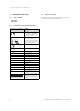
10 Technical data 10 Technical data 10.1 Technical data table Number of tubes η0 (Aperture), DIN4757-4 or EN12975 Unit VTK 570/2 VTK 1140/2 − 6 12 % 64.2 c1 with wind, or on aperture W/(m²k) 0.885 c2 with wind, or on aperture W/(m²k²) 0.001 K θ,trans (50°), or on aperture − 1 K θ,long (50°), or on aperture − 0.
Technical data 10 10.
10 Technical data 1652 111 1392 10.
Technical data 10 Efficiency of the VTK 570/2 and the VTK1140/2 at a solar energy input EG of 800 W/m2 η 80% 70% 60% 50% 40% 30% 20% 10% 0% ΔT 0 η 5 10 15 20 25 30 35 40 45 ΔΤ Efficiency [%] 50 55 60 65 70 75 80 Τcollector −ambient air Τ [K] Pressure loss Δp [mbar] 160 140 120 VTK 570/2 VTK 1140/2 100 90 60 40 20 0 0 Q 50 100 150 200 250 Mass flow [l/h] 0020077994_02 auroTHERM exclusive Installation manual 300 Δp 350 400 450 Q [l/h] 500 Pressure loss [mbar] 67
Index Index H A Hydraulic connections Installing............................................................................ 29, 54 Applicability Manual .........................................................................................5 Article numbers ...............................................................................5 I Identification plate ........................................................................ 10 B Installation clearances Complying with .......................
Index Spare parts Maintenance............................................................................ 57 Troubleshooting ..................................................................... 59 T Technical data ............................................................................ 64 Dimensions .............................................................................. 65 Efficiency ................................................................................. 66 Pressure loss..............
0020077994_02