Operating instructions For the operator Operating instructions uniSTOR domestic hot water cylinder GB, IE
the nation’s favourite for PLUMBING & HEATING SUPPLIES FREE SHIPPING SECURE PAYMENTS on all orders over £100 to mainland UK shop online with confidence FINANCE AVAILABLE PRICE MATCH spread the cost with low interest rates always get the best deals available we have H U G E R E D U C T I O N S ON THOUSANDS OF ITEMS Boilers Bathroom suites Radiators Kitchen sinks & taps Heating controls Showers Pipes & ittings Wet rooms Cylinders Towel warmers Fires Bathroom furniture Renewable energy
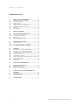
Table of contents Inhaltsverzeichnis 1 1.1 1.2 1.3 1.4 1.5 1.6 1.7 Notes on the documentation ................................ 3 Other applicable documents ................................... 3 Storing documents ..................................................... 3 Symbols used ............................................................... 3 Applicability of the instructions .............................. 3 Cylinder identification plate ..................................... 3 CE label .................
Notes on the documentation 1 1 Notes on the documentation The following instructions are intended to guide you through the entire documentation. Further documents apply in combination with these operating instructions. We do not accept liability for any claims or damages resulting from failure to observe these instructions. 1.1 Other applicable documents > When operating the cylinder, observe all of the operating instructions delivered with other system components. 1.
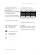
2 Safety instructions 1.7 Benchmark 2 Safety instructions 2.1 Safety and warning information When operating the system, observe the basic safety instructions and the warning notes which appear before each of the actions. Fig. 1.1 Benchmark logo Benchmark places responsibilities on both manufacturers and installers.
Safety instructions 2 2.2 Intended use Vaillant cylinders are constructed using state-of-the-art technology in accordance with recognised safety regulations. Nevertheless, there is still a risk of injury or danger of death to the operator or others or of damage to the unit and other property in the event of improper use or use for which the unit is not intended.
3 Description of the unit 3 Description of the unit 3.1.3 Functional elements of cylinder The Vaillant uniSTOR domestic hot water cylinder is available in six sizes: 120, 155, 180, 210, 260 or 310 litres and meets the requirements of EN 12897:2006. The cylinder is made from stainless steel and is insulated with EPS with heat radiation absorbers. The unvented domestic hot water cylinder works with the pressure of the water supply line and does not need a cold water tank for its supply.
Operation 4 4 Operation a Danger! Risk of scalding and bursts due to inappropriate alterations! There is a risk of escaping steam, bursting, and damage to the system if you make any changes to the cylinder, control system, supply lines for water and power (if present), relief valve termination, or expansion relief valve for the cylinder water. > Do not make any improper changes.
4 Operation i i If you are heating up water for the first time or after a long switch-off period, the full cylinder performance is only available following a waiting period. i Always make sure that there is clear access to the cylinder to enable the use of the hot water thermostat controller and the thermostat mixer. 4.
Operation 4 4.7 Energy-saving tips Appropriate hot water temperature The warm water should only be heated up to the extent that is necessary for use. Any further heating results in unnecessary power consumption and hot water temperatures of more than 60 ºC also lead to increased lime scale production. Run circulation pumps only if needed Circulation pumps do indeed increase convenience when it comes to hot water production. But they also need power.
5 Inspection and maintenance 6 Recycling and disposal 5 Inspection and maintenance An annual inspection/maintenance carried out by a competent person is a prerequisite for ensuring that the cylinder is permanently ready for operation, reliable, and has a long working life. It is important that your hot water cylinder is serviced annually. We recommend entering into a maintenance agreement.
Customer service and manufacturer's guarantee 7 7 7.1 Customer service and manufacturer's guarantee Vaillant service To ensure regular servicing, it is strongly recommended that arrangements are made for a Maintenance Agreement. Please contact Vaillant Service Solutions (0870 6060 777) for further details. 7.2 Vaillant warranty Vaillant provides a full parts and labour warranty for this appliance.
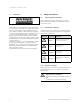
8 Technical data 8 Technical data Unit Total capacity Actual capacity Hot water capacity Maximum supply pressure to pressure reducing valve Rated pressure of cylinder Maximum operating pressure of heating coil Operating pressure Pressure reducing valve Expansion relief valve Temperature and pressure relief valve Charge pressure of hot water expansion vessel Maximum temperature of heating circuit Maximum temperature of potable hot water Standing heat loss Heat up time according to EN 12897 Recovery time (
i The heat up time is based on a flow rate of 1400 l/h at 80 ºC. Temperature rise from 15 ºC to 60 ºC.
Supplier Manufacturer 0020111106_00 GBIE 062011 – Subject to change
Installation and maintenance instructions For the competent person Installation and maintenance instructions uniSTOR VIH /2 S GB, IE
Table of contents Inhaltsverzeichnis 1 1.1 1.2 1.3 1.4 1.5 1.6 1.7 Notes on the documentation ................................ 3 Other applicable documents ................................... 3 Storing documents ..................................................... 3 Symbols used ............................................................... 3 Applicability of the instructions .............................. 3 Cylinder identification plate ..................................... 3 CE label .................
Notes on the documentation 1 1 Notes on the documentation The following instructions are intended to guide you through the entire documentation. Other documents apply in addition to these operating instructions. We do not accept liability for any claims or damages resulting from failure to observe these instructions. 1.1 Other applicable documents > When installing the cylinder, you must pay attention to the installation instructions for components of the system. 1.
1 Notes on the documentation 2 Safety instructions and regulations 1.7 Benchmark 2 Safety instructions and regulations 2.1 Safety and warning information When conducting installation and maintenance work, observe the general safety instructions and the warning notes which appear before each of the actions. Fig. 1.1 Benchmark logo Benchmark places responsibilities on both manufacturers and installers.
Safety instructions and regulations 2 2.2 Intended use Vaillant cylinders are constructed using state-of-the-art technology in accordance with recognised safety regulations. Nevertheless, there is still a risk of injury or danger of death to the operator or others or of damage to the unit and other property in the event of improper use or use for which the unit is not intended.
2 Safety instructions and regulations If the water does not meet the requirements of The Water Supply (Water Quality) Regulations 2000 (Amendment) Regulations 2007, corrosion damage may occur on the cylinder. > Only use the cylinder to heat potable water. Electric potential equalisation If you use an electric immersion heater in the cylinder, the external voltage may build up electrical potential in the water which can result in the electrochemical corrosion of the electric immersion heater.
Safety instructions and regulations 2 EC low voltage directive 2006/95/EC Directive 2006/95/EC of the European Parliament and Council of 12th December 2006 on the harmonisation of the laws of Member States relating to electrical equipment designed for use within certain voltage limits Lightning protection ENV 61024-1 Protection of structures against lightning – Part 1: General principles (IEC 1024-1: 1990; modified) BS 6651: Code of practice for protection of structures against lightning 2.
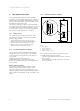
3 Description of the unit 3 Description of the unit 3.1 Description of the cylinder DHW 8 2 3 M 4 7 6 1 M 5 A M B 5 Fig. 3.
Description of the unit 3 1 2 3 20 4 7 6 5 9 4 3 2 5 1 8 3 19 18 17 16 15 14 13 12 10 11 Fig. 3.2 Functional elements of uniSTOR domestic hot water cylinder Key 1 Hot water draw off 2 Expansion relief valve (one-way valve, 6.0 bar) 3 Pressure reducing valve (3.
3 Description of the unit The uniSTOR domestic hot water cylinder is available in six sizes: 120, 155, 180, 210, 260, and 310 litres. The cylinder is made from stainless steel and is insulated with EPS with heat radiation absorbers. The cylinder is supplied along with all required cold and hot water control devices and a two port motorised valve. The cylinder works with the pressure of the water supply line and does not need a cold water tank for its supply.
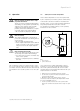
Description of the unit 3 3.1.3 Electric immersion heater Setting Hot water temperature 1 1 2 4 20 °C 2 35 °C 3 45 °C 4 60 °C 5 68 °C 3 2 Table 3.1 Setting the hot water temperature 3 5 3.1.4 Hot water temperature regulation 1 You can control the hot water temperature using a Vaillant dual-channel eBUS controller or a separate hot water controller. a Fig. 3.
3 Description of the unit 3.
Description of the unit 3 i The heat up time is based on a flow rate of 1400 l/h at 80 °C. Temperature rise from 15 ºC to 60 ºC. Dimensions 1 2 4 b 5 c a 3 6 633 h g f e Ø 554,5 d 7 25° i 45° Fig. 3.
4 Installation 4 Assembly 4.1 4.2 Transporting the cylinder Scope of delivery a 8 7 Danger! Risk of injury due to heavy load! Heavy load can cause injuries. > At least two people should lift the cylinder to prevent injuries. > Use a suitable transportation aid (sack truck or similar). 6 1 5 > Transport the packaged cylinder to the installation site. > Only remove the cylinder from its packaging once it reaches the installation site. 4 4.
Installation 5 5 Installation a Danger! Risk of injuries and damage due to improper installation! Improper installation can impede the operational safety of the unit. > Only a competent person may install and commission the unit. This person takes responsibility for making sure that the unit is installed and commissioned for the first time correctly and in accordance with regulations. 5.
5 Installation 5.2 Installing hot water pipes > Connect the hot water piping to the 22 mm hot water draw off of the cylinder. > Lay the 22 mm piping up to the first T-piece. The required diameter of subsequent pipes depends on the system design. Installing the circulation line 2 1 5.3.1 Pressure in cold mains inlet The efficiency of an unvented cylinder depends on the available pressure in the cold mains inlet and the flow rate.
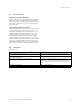
Installation 5 5.3.2 Mounting the safety assembly b Caution! Risk of damage to the cylinder as a result of excess pressure! Excess pressure can cause the cylinder to burst. > Make sure that there is no stop valve installed between the safety assembly and the cylinder. 1 7 6 > Mount the discharge pipe of the expansion relief valve with a constant slope to the outside.
5 Installation 5.3.4 Mounting the drain valve > Mount a drain valve (10) (¬ fig. 3.2) as low as possible between the cylinder and the safety assembly in the cold mains inlet. Safety valve (e.g. Temperature and pressure relief valve) Metal discharge pipe (D1) from temperature and pressure relief valve to tundish Max. 600 m m The drain valve must be provided by the customer. We recommend mounting a hose which reaches about 1 m under the base of the cylinder to the outlet of the drain valve.
Installation 5 Worked example The example below is for a G1/2 temperature relief valve with a discharge pipe (D2) having 4 No. 22 mm elbows and length of 7 m from the tundish to the point of discharge. From Table 5.1: Maximum resistance allowed for a straight length of 22 mm copper discharge pipe (D2) from a G1/2 temperature relief valve is: 9.0 m. Subtract the resistance for 4 No. 22 mm elbows at 0.8 m each = 3.2 m Therefore the maximum permitted length equates to: 5.
5 Installation 5.5 Electrical installation e Danger! Risk of death from electric shock! Improperly executed electrical connections can impair the operational safety of the unit. > The electrical installation may only be performed by a competent person approved at the time by the Health and Safety Executive. 5.5.
Installation 5 5.5.2 Connecting up the electric immersion heater 1 7 1 2 4 2 6 3 2 5 3 5 4 3 1 4 5 Fig. 5.
5 Installation > Remove the top front cladding from the cylinder. > Dismantle the electric immersion heater cover. > Install a separate electrical power supply for the electric immersion heater in accordance with current IEE regulations (BS 7671). – Use heat-resistant cables (1.5 mm2, 3-wire HOFR-coated) as per BS 6141 for the cabling of the electric immersion heater. – Use the cable grip (2) to firmly secure the supply cable of the immersion heater.
Installation 5 Connection wiring diagram Gas-fired wall-hung boiler Wiring via Control system of the heating circuits Regulation of cylinder reheating Hydraulic plan Vaillant ecoTEC, eBUS-compatible VR 65 Vaillant dual-channel eBUS controller Vaillant dual-channel eBUS controller with VR 65 S plan 1 ¬ fig. 5.10 Vaillant dual-channel eBUS controller Vaillant dual-channel eBUS controller with VR 65 Y plan 2 ¬ fig. 5.11 Programmable timer and room thermostat Timer S or Y plan 6 ¬ fig. 5.
5 Installation 5.5.4 Installing the control components in accordance with the connection wiring diagrams Connection wiring diagram 1 (S plan) PE N L PE N on off on PE N on + NTC BUS DHW DHW CH CYL. 230 V grid VR 65 - 2 1 DO NOT USE PE 3A 2 N L 2 Cylinder NTC Vaillant ecoTEC BUS C 12 Cylinder thermostat and TCO DHW M PE Blue Brown M PE Blue Brown CH + 2 Vaillant dual-channel eBUS controller BUS + Fig. 5.
Installation 5 – eBUS-compatible Vaillant gas-fired wall-hung boiler – Wiring via Control Center VR 65 – Primary heating circuit control via Vaillant dual-channel eBUS controller – Room heating control via Vaillant dual-channel eBUS controller – S plan > Next to the domestic hot water cylinder, install the Control Center VR 65. > Dismantle the cover of the VR 65. i The terminals NTC and CYL. of the VR 65 may not be connected at the same time.
5 Installation Connection wiring diagram 2 (Y plan) PE N L PE N on off on PE N on + NTC BUS DHW DHW CH CYL. 230 V grid VR 65 - 2 1 DO NOT USE PE 3A 2 N L 2 Cylinder Vaillant ecoTEC BUS C 12 Cylinder thermostat and TCO PE Blue Brown or white Grey Orange M NTC + 2 Vaillant dual-channel eBUS controller BUS + Fig. 5.
Installation 5 – eBUS-compatible Vaillant gas-fired wall-hung boiler – Wiring via Control Center VR 65 – Primary heating circuit control via Vaillant dual-channel eBUS controller – Room heating control via Vaillant dual-channel eBUS controller – Y plan Connect the cylinder to the standard cabling box (S plan or Y plan hydraulics) The cylinder thermostat can be connected to S plan or Y plan hydraulics by means of standard cabling.
5 Commissioning 6 6.1 Commissioning 6.2 Water treatment Flushing the reheating circuit Detailed recommendations for the water circuit can be found in BS 6798 and BS 5449: Part 1 (for central heating systems with both small and the smallest pipe width). Pipes which do not form part of the usable heating surface must be insulated in order to prevent heat losses and possible freezing. Pipe insulation is particularly important if you are installing pipes under the roof or in open areas under the floor.
Commissioning 6 > Inform the operator of the necessary measures if you have used these additives. > Inform the operator about the required measures for frost protection. > Observe all valid national and technical regulations when treating the filling and supplementary water.
6 Commissioning 6.4 Filling the central heating system The system can be filled using the built-in filling loop (ecoTEC plus combi boiler only) or via a separate filling connection that is fitted at an easily accessible location in the heating circuit. The filling loop must be removed once filling is complete. If a temporary connection is not possible due to legal regulations, a closed system filling pump with a buffer tank must be used.
Commissioning 6 6.5 Commissioning the gas-fired wall-hung boiler > Make sure that the control device and thermostats are set so that heating is required. > Carry out the commissioning and testing measures for the gas-fired wall-hung boiler in accordance with the installation instructions. > Check whether the gas-fired wall-hung boiler starts operating and the water in the cylinder and radiators heats up in accordance with the hot water and room thermostat settings.
7 Inspection and maintenance 7 Inspection and maintenance Regular inspections and maintenance of the cylinder by a competent person approved at the time by the Health and Safety Executive are a prerequisite for long-lasting operational readiness, reliability and a long working life. The operational reliability of the cylinder may be impaired and material damage and personal injuries may result if the inspection and maintenance work is not carried out.
Fault finding 8 8 Fault finding The tables below provide information on possible faults which can occur when the cylinder is being operated along with information on their causes and how to rectify them. All work on the Vaillant cylinder (installation, maintenance, repairs etc.) may only be performed by competent persons. a Danger! Risk of death from electric shock! Improperly executed work on the cylinder can result in a risk to life and limb.
8 Fault finding Fault The cylinder cools down at night. Primary heating is not working. The gasfired wall-hung boiler runs for a short time, goes off, and then comes back on again. This is repeated until the cylinder is at its target temperature. Only cold or lukewarm water comes out of the draw-off points. Cause One-pipe circulation in the case of short tube networks with low pressure loss. 1. Air in the reheating heat exchanger. 2. Heat exchanger surface area too small. 1.
Taking the cylinder out of service 9 Recycling and disposal 10 9 Taking the cylinder out of service 9.1 Temporarily taking the cylinder out of service b Caution! Risk of damage as a result of the cylinder freezing! Frost protection and monitoring devices are only active while the boiler is connected up to the power supply. > Make sure that the cylinder cannot be damaged if there is a frost.
11 Customer service and manufacturer's guarantee 11 11.1 Customer service and manufacturer's guarantee Vaillant service To ensure regular servicing, it is strongly recommended that arrangements are made for a Maintenance Agreement. Please contact Vaillant Service Solutions (0870 6060 777) for further details. 11.2 Vaillant warranty Vaillant provide a full parts and labour warranty for this appliance - please see warranty card for details.
Commissioning checklist and service record
MAINS PRESSURE HOT WATER STORAGE SYSTEM COMMISSIONING CHECKLIST This Commissioning Checklist is to be completed in full by the competent person who commissioned the storage system as a means of demonstrating compliance with the appropriate Building Regulations and then handed to the customer to keep for future reference. Failure to install and commission this equipment to the manufacturer’s instructions will invalidate the warranty but does not affect statutory rights.
SERVICE RECORD It is recommended that your hot water system is serviced regularly and that the appropriate Service Record is completed. Service Provider Before completing the appropriate Service Record below, please ensure you have carried out the service as described in the manufacturer’s instructions.
Supplier Manufacturer 0020111105_00 GBIE 062011 – Subject to change