Installation instructions For the competent person Installation instructions VR 66 Control Centre VR 66 GB, IE
TABLE OF CONTENTS 1 Notes on the documentation ......................................................................................................... 2 1.1 1.2 1.3 1.4 2 Safety.......................................................................................................................................... 2 2.1 2.2 2.3 2.4 3 Product Overview ................................................................................................................4 Product structure ....................
INTRODUCTION 1 Notes on the documentation 1.1 The symbols used in the text are explained below: Explanation i ∙ Symbol that denotes useful tips and information Warning symbol Signal word 1.2 Explanation Immediate danger to life or risk of severe personal injury. Danger Danger Risk of death from electric shock. Warning Risk of minor personal injury. Caution Risk of material or environmental damage.
INTRODUCTION 2.1.5 Danger of scalding due to the hot water! ∙ There is a danger of scalding at the hot water draw-off points if the hot water temperatures are higher than 60°C. Young children and elderly persons are particularly at risk, even at lower temperatures. ∙ Select the temperature so that nobody is at risk. ∙ Explain to the user how to select the best temperature taking into account the risk of scalding and the risk of legionella. 2.1.
INTRODUCTION - The Health and Safety at Work Act, Control of Substances Hazardous to Health (COSHH). - Any electrical work must conform to BS7671 and part P of the building regulations where applicable. 2.4 Where no specific instructions are given, reference should be made to the relevant British Standard Code of Practice. - European Directive Num.
INTRODUCTION 3.2 Product structure 3.2.1 Monozone operation mode The Monozone operation mode is compatible with: - eBUS controllers range (VRT 392, VRT 392f, VRT 350, VRT 350f, VRC 430, VRC 430f, VRC 470, VRC 470f) - System and open vent boiler It allows the controller to communicate with the traditional 230V zone valves and DHW storage cylinder. Information about the heat required by the cylinder is communicated to the heating appliance.
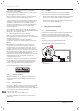
INTRODUCTION 3.2.3 Monozone mode : Open vent or system boiler with DHW cylinder, 3-Port Valve 1 EBUS 1 5 D 7 EBUS 4 2 8 9 1 C 10 A 6 4 B 11 1m min. DHW cylinder with NTC DHW cylinder with thermostat 5 CYL.
INTRODUCTION 3.2.4 Monozone mode : Open vent or system boiler with DHW cylinder : two 2-Port Valves 1 EBUS 1 6 D 8 EBUS 5 2 9 10 1 C 11 3 A 7 12 B 4 1m min. DHW cylinder with NTC DHW cylinder with thermostat 6 CYL.
INTRODUCTION 3.2.5 Multizone operation mode The Multizone operation mode is compatible with: - VRT350 - system, combi and open vent boiler The information about the heating or hot water demand is sent to the room thermostat via the control unit to the boiler. The VR66 then decides if the hot water demand needs to be fulfilled and drives the valves. In this way, the boiler can store different target temperatures for heating and hot water modes. i The multizone mode is only compatible with VRT350.
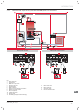
INTRODUCTION 3.2.6 Multizone mode : Open vent or system boiler with DHW cylinder 0 EBUS 0 EBUS 3 10 EBUS 15 D 12 9 2 6 5 13 1 C 16 7 A 11 14 B 8 1m min. DHW cylinder with NTC DHW cylinder with thermostat 10 CYL. 230V~ CH1 DHW ON 10 DHW OFF CH2 BUS + 2 CYL.
INTRODUCTION 3.2.7 Multizone mode with combi boiler 0 EBUS 0 EBUS 1 8 9 EBUS 7 2 5 3 10 C D A 11 B 6 8 CYL.
INSTALLATION 3.3 Type designation and serial number Do not install the control unit: - close to heat sources such as radiators, chimney walls, televisions, direct sunlight, Data plate location: - above a cooking device capable of generating steam and grease, - in a room with a lot of dust or with a corrosive atmosphere. 1 3.4 b Caution! These pipes can become very hot which will damage the cables or the system. • The electrical cables must not be attached to or in contact with the hydraulic pipes.
INSTALLATION 4.2.2 Wall-mounting of the product The control unit is designed to be attached to a wall near the main tank inside a dwelling. 235 2 3 3 1 2 appliance earthing. This includes failure to comply with current standards. b Caution! These pipes can become very hot which will damage the cables or the system. • The electrical cables must not be attached to or in contact with the hydraulic pipes. 4.3.
INSTALLATION 5.2 24V connectors (low voltage) Venting 5.2.1 Boiler Commission the boiler according to the instructions of its installation manual. CYL. 230V~ CH1 DHW ON DHW OFF CH2 BUS + 2 - NTC 2 ∙ Refer to the installer manual. 1 1 5.2.2 Heating circuit adjustement Venting of the heating circuit enables the purging of any air in the heating circuit (valves still manually opened). BUS + Key 1 eBUS connector (2 pins) 2 NTC connector (2 pins) 4.3.
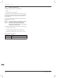
MAINTENANCE 6 User information At the end of the installation, the installer must: Fault Possible cause Solution Green LED permanently off No 230 V power supply or the fuse in the appliance is faulty Check that the main voltage cable is connected correctly. Check the domestic fuse for the 230 V supply and re-connect the power supply. Replace the main supply fuse in the control unit (see technical data).
TECHNICAL DATA 8 Decommissioning ∙ Switch off the product. ∙ Isolate the product from the power mains. ∙ De-install the product. ∙ Recycle or dispose the product and its components (see chapter 9). 9 9.1 Recycling and disposal Recycle the packaging - Sort the waste to separate those which can be recycled (cartons, plastics...) from those that cannot (strapping ...). - Recycle the product packaging according to all relevant regulations. 9.
Supplier Manufacturer 0020140122_02 - 05/13 Subject to engineering changes