
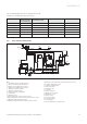
Technical data


Installation and maintenance instructions ecoCRAFT - 0020055744_0318
e
Danger!
Danger of death from electric shock!
The fan is connected to a 230 V/50 Hz supply.
The connection should be wired as follows:
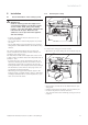
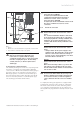
• Open the front flap by lifting the silver handle strip.
• Unscrew the screw above the multi-function operating
panel.
• Pull the front casing in the upper section towards you
and lift it in order to remove it.
• Hinge the electronics box forward.
• Unclip the rear part of the electronics box cover and
hinge it upwards.
• Pass the cables through the cable entry in the rear
wall of the appliance and through the unit into the
electronics box.
• Use the cable channel on the left hand side section for
feeding the cable through the unit.
a
Caution!
Risk of malfunction!
Do not use the same strain relief for the extra
low voltage cable as for the mains cable!
• Take care to ensure spatial separation of the mains
and extra low voltage cables.
• Secure the cables with the strain reliefs.
• Carefully strip the insulation from the cable ends.
• Then close the rear cover of the electronics box and
press it down until it audibly engages.
• Hinge the electronics box up.
• Fasten the front casing.
• Screw the screw above the multi-function operating
panel in again.
• Close the front cover.
5.9.1 Connecting the mains cable
The nominal voltage of the mains must be 230 V; if the
mains voltage is more than 253 V or below 190 V, func-
tional impairment is possible. The mains feed must be
connected via a fixed connection and an isolating device
having a minimum contact opening of 3 mm (e.g. fuses,
power switches).
• Connect the mains cable to the terminals provided, N,
L and PE, in the plug.
h
Note
Ensure that the boiler room complies wit the
requirements of BS 664 and IGE UP10.
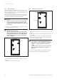
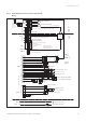
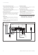
5.9.2 Connecting a controller
The Vaillant VRC 630 controller or an externally mount-
ed Vaillant VRC 430 controller must be connected via
the "Bus" connection (red plug) in accordance with Fig.
5.8 or Fig. 5.9. The bridge between the terminals 3 and
4 should remain intact (lilac plug).
The sensors and the system components that are not
listed in Section 5.10.3 are connected to the controller.
The electrical connection to the Vaillant heating control
unit is shown in Fig. 5.7.
Further information can be obtained from the regulator
instructions.
5 Installation