
Technical data


33Installation and maintenance instructions ecoCRAFT - 0020055744_03
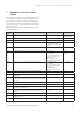
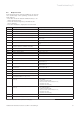
No. Procedure Remarks Tools
1 Check the filling pressure of the heating system
(button
"-")
Top up if necessary (approx. 2.5 bar)
2 Visual check for leaks in heating circuit Check function of quick vent system
3 Visual check of safety valve In accordance with BS 6644
4 Check condensate collector, siphon, supply air and flue
gas paths for contamination and leaks. Check gaskets
of the condensate trough, the inspection opening and
between the flue gas flange and the heat exchanger for
damage and replace if necessary.
See: 8.5 and 8.6
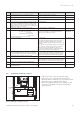
5 Switch on the appliance - call up test program P1 = rated load, P2 = minimum load
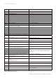
6CO
2
measurement (target value:
at rated load: 9.3 % Vol.
(±0.2 % Vol.)
at minimum load: 9.0 % Vol.
(±0.2 5 Vol.)
CO measurement (target value < 80 ppm)
If the values are not within this range,
you need to perform a CO
2
adjustment before the
inspection can continue (see: 6.4.3)
CO
2
-measuring
instrument
7 Capacity measurement Gas rate check
If the capacity is more than 15 % below the nominal
value, then the burners must be cleaned or replaced
Every time the burner is dismantled, replace the
gaskets and tighten the burner flange to 12 Nm on the
diagonal.
After cleaning or replacing the burner, a new measure-
ment of the CO
2
value and the loading is required. If
necessary, the
CO
2
value will have to be re-set.
Check for gas leaks behind the fan and along all the
burner gaskets with gas sensing equipment.
Gas sensing
equipment
8 Check flue gas pressure monitor, visual check of all
tubes and measuring nipples, functional check by flue
gas full block with flue gas baffle or similar equipment
At nominal capacity and full blockage the burner must
go out after latest two minutes, and then thereafter
continuous automatic re-starting. No flue gas should
escape to the installation room through the syphon.
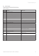
9 Check syphon and condensate drain for leaks
10 Check flue gas piping for leaks Visual check of connection and fixing fittings. No con-
densate should drip out of the connection points, pipes
have a gradient of > 3° in the direction of the boiler.
11 Replace casing components, fully assemble boiler
12 Unit off - switch unit on - check function of regulator
(hot water/heating)
Table 8.1 Inspection Checklist
Maintenance 8
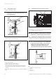
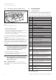
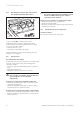
8.6 Cleaning the condensate collector
1
Fig. 8.1 Cleaning the condensate collector
• Remove the front section of the boiler casing.
• Remove the cover on the inspection opening (1).
• Check the water condensate collector for dirt contam-
ination and clean if required with a scraper.
• Check the gasket on the inspection opening for dam-
age before re-assembly. If required, a new gasket
should be fitted.