83 41 77_12 GB04.04.qxd 22.09.
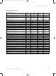
83 41 77_12 GB04.04.qxd 22.09.2004 12:34 Uhr Seite 2 Table of contents 1 1.1 1.2 1.3 Introduction . . . . . . . . . . . . . . . . . . . . . . . . Introduction . . . . . . . . . . . . . . . . . . . . . . . . . . . . General notes . . . . . . . . . . . . . . . . . . . . . . . . . . . EC designation . . . . . . . . . . . . . . . . . . . . . . . . . . 4 4 4 4 2 2.1 2.2 2.3 2.4 2.5 2.6 2.7 Boiler specification . . . . . . . . . . . . . . . . . . . Technical data . . . . . . . . . . . . . . . . . . . . .
83 41 77_12 GB04.04.qxd 22.09.2004 12:34 Uhr Seite 3 Table of contents 7 7.1 7.2 7.2.1 7.2.2 7.2.3 7.2.4 7.2.5 7.2.6 7.3 7.4 Servicing . . . . . . . . . . . . . . . . . . . . . . . . . . . Inspection and maintenance . . . . . . . . . . . . . . . Initial inspection . . . . . . . . . . . . . . . . . . . . . . . . Removing the compact thermal module . . . . . Inspect main heat exchanger . . . . . . . . . . . . . . Inspect burner . . . . . . . . . . . . . . . . . . . . . . . . . .
83 41 77_12 GB04.04.qxd 22.09.2004 12:34 Uhr Seite 4 1 Introduction 1 Introduction 1.2 General Notes The boilers have been designed for use with a sealed 1.1 Introduction central heating system, and come fully tested and assembled with a built in circulating pump, expansion Note: vessel and diverter valve (ecoMAX 800).
83 41 77_12 GB04.04.qxd 22.09.2004 12:34 Uhr Seite 5 Boiler Specification 2 Boiler Specification 2 2.1 Technical data (1) Maximum CH heat input (G 20) (net) Maximum CH heat input (G 31) (net) CH heat output range 80 °C flow/60 °C return 50 °C flow/30 °C return SEDBUK SAP Seasonal Efficiency Maximum DHW heat input (net) Maximum DHW output DHW flow rate ∆T = 35 K rise Appr. DHW flow rate at factory set temp. rise (DT = 42 °C) Mains water pressure required for max.
83 41 77_12 GB04.04.qxd 22.09.2004 12:34 Uhr Seite 6 2 Boiler Specification 2.1 Technical data (2) ecoMAX Maximum CH heat input (G 20) (net) Maximum CH heat input (G 31) (net) CH heat output range 80 °C flow/60 °C return 50 °C flow/30 °C return SEDBUK SAP Seasonal Efficiency Inlet gas working pressure required (natural gas) Inlet gas working pressure required (Propane) Gas supply (G20) Gross CV (s.t.) Gas supply (G31) Gross CV (s.t.) Gas rate (natural gas) max. Gas rate (Propane) max.
83 41 77_12 GB04.04.qxd 22.09.2004 12:34 Uhr Seite 7 Boiler Specification 2 2.3 Boiler connections 2.4 Scale drawing and fitting dimensions Dimensions when combined with A 150 703 the following system comp.: 750 70 ØB C* with 87° elbow air/flue system Ø 60/100 235 60/100 _ air/flue system Ø 80/125 253 80/125 _ VANTAGE 120 _ _ 1101 VANTAGE 150 _ _ 1101 VANTAGE 200 _ _ _ Tab. 2.
3 41 77_12 GB04.04.qxd 22.09.2004 12:34 Uhr Seite 8 2 Boiler Specification 2.5 Functional diagrams 28 1 27 28 1 27 2 2 3 3 4 5 6 26 4 25 5 6 26 25 24 24 7 7 8 8 23 23 22 22 21 21 20 20 19 18 9 10 11 12 10 17 13 Fig. 2.
83 41 77_12 GB04.04.qxd 22.09.2004 12:34 Uhr Seite 9 Boiler Specification 2 2.6 Design 1 13 1 13 2 12 2 12 3 3 4 11 5 6 10 9 4 11 10 9 7 8 Fig. 2.
83 41 77_12 GB04.04.qxd 22.09.2004 12:34 Uhr Seite 10 2 Boiler Specification 3 General requirements 2.7 Identification plate The identification plate of the Vaillant ecoMAX is supplied ready–attached to the bottom of the unit. Fig. 2.8 Identification plate (example) 3 General requirements 3.1 Preliminary remarks This appliance should only be installed in conjunction with a Vaillant flue system. Install the flue system as detailed in the separate flue installation instructions supplied with this boiler.
83 41 77_12 GB04.04.qxd 22.09.2004 12:34 Uhr Seite 11 General requirements 3 3.3 Contents included with boiler (ecoMAX 800/2) Ensure that all contents are included before commencing installation. 2 3.4 Contents included with boiler (ecoMAX 600/2) Ensure that all contents are included before commencing installation. 2 3 1 3 1 4 4 5 10 5 6 10 6 7 9 8 9 7 Fig. 3.1 Items supplied with unit (ecoMAX 800) Fig. 3.
83 41 77_12 GB04.04.qxd 22.09.2004 12:34 Uhr Seite 12 3 General requirements 3.6 Gas supply The gas supplier should ensure the availability of an ade–quate supply of gas. A gas meter may only be connected to the service pipe by the supplier of gas or their contrac–tor. An existing meter should be checked to ensure that it is capable of passing the rate of gas supply required. Installation pipes should be fitted in accordance with BS 6891. In IE the current edition of IS 813.
83 41 77_12 GB04.04.qxd 22.09.2004 12:34 Uhr Seite 13 General requirements 3 1103 15 70 70 3.8 Flue termination The following details refer to both flue systems. a. The terminal must be positioned such that the products of combustion can disperse freely at all times. b. A plume of water vapour will sometimes be visible from the flue terminal. Positions where this could be a nuisance should be avoided. c.
83 41 77_12 GB04.04.qxd 22.09.2004 12:34 Uhr Seite 14 3 General requirements Note: In addition, the terminal should not be nearer than 150 mm to an opening in the building fabric formed for the purpose of accommodating a built–in element such as a window.
83 41 77_12 GB04.04.qxd 22.09.2004 12:34 Uhr Seite 15 General requirements 3 3.11.5 Expansion vessel ecoMAX boilers incorporate a 10 litre expansion vessel which is suitable for a sealed heating system with a maximum water content of 100 litres. If the nominal capacity of the built in expansion vessel is not sufficient for the heating system (for instance in case of modernization of old open systems) an additional expansion vessel can be installed external to the boiler.
83 41 77_12 GB04.04.qxd 22.09.2004 12:34 Uhr Seite 16 4 Boiler installation sequence 4 Boiler installation sequence min 205/220* 4.1 General min 5 min 500** min 5 4.1.1 Select position of boiler Refer to section ‘Boiler location’ for information regarding siting the appliance. In general the boiler must be positioned such that: • There is adequate space around the boiler for service and maintenance • The boiler can be correctly flued, i.e.
83 41 77_12 GB04.04.qxd 22.09.2004 12:34 Uhr Seite 17 Boiler installation sequence 4 4.2 Rear flue exit Mark the position of the air/flue duct and its circumference. 4.3 Other flue options Flue instructions for other flue systems such as vertical RSF flues, flues run to the side of the boiler and the use of additional bends etc. are detailed in the flue installation instructions provided with the boiler. Remove the template from the wall and plug the drilled holes using the wallplugs supplied.
83 41 77_12 GB04.04.qxd 22.09.2004 12:34 Uhr Seite 18 4 Boiler installation sequence 4.6 Fitting the boiler • Lift the boiler (3) up to the wall so that it is slightly above the hanging bracket (1). 4.8 Cold water mains inlet and hot water outlet (ecoMAX 800) Note: Lift the boiler from either side at the bottom edge. • Lower the boiler slowly onto the hanging bracket so that the cross member at the rear of the boiler fully engages onto the hanging bracket. 4.
83 41 77_12 GB04.04.qxd 22.09.2004 12:34 Uhr Seite 19 Boiler installation sequence 4 4.9 Gas supply 4.10 Central heating flow and return pipework Fig. 4.6 Fitting the gas connection ecoMAX 800 (picture shows ecoMAX 800) Fig. 4.7 Central heating flow and return pipework (picture shows ecoMAX 800) • Connect the compression gas service cock and 15 mm copper outlet tail as supplied with the appliance and tighten. • Connect a gas supply pipe of not less than 15 mm diameter to the copper tail.
83 41 77_12 GB04.04.qxd 22.09.2004 12:34 Uhr Seite 20 4 Boiler installation sequence 4.11 Pressure Relief Valve (ecoMAX 800) 4.12 Pressure Relief Valve (ecoMAX 600) Fig. 4.8 Fitting the pressure relief valve (ecoMAX 800) Fig. 4.9 Fitting the pressure relief valve (ecoMAX 600) The pressure relief valve and filling loop connection is provided within the boiler cardboard box and should be assembled as shown below. • Remove plug from connection (1).
83 41 77_12 GB04.04.qxd 22.09.2004 12:34 Uhr Seite 21 Boiler installation sequence 4 4.13 Condensate drain (fig. 4.10) Connect the boiler condensate drain (1) to the condensate discharge pipe (2) the condensate discharge pipe should be minimum of 19mm internal diameter (22mm external diameter for any pipework installed external to the property) and be made of an acid resistant material (e.g. plastic overflow pipe).
83 41 77_12 GB04.04.qxd 22.09.2004 12:34 Uhr Seite 22 4 Boiler installation sequence 4.16 Electrical installation 4.16.1 General requirements All electrical work shall be carried out by a competent person and shall comply with BS7671 (IEE Regulations). In IE, reference should be made to the current edition of the ETCI rules. The boiler is supplied for connection to 230 V, ~ 50 Hz supply fused at 3 A rating.
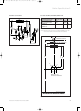
83 41 77_12 GB04.04.qxd 22.09.2004 12:34 Uhr Seite 23 Boiler installation sequence 4 4.16.3 Electronic board layout4.16.
83 41 77_12 GB04.04.qxd 22.09.2004 12:34 Uhr Seite 24 4 Boiler installation sequence 4.16.
83 41 77_12 GB04.04.qxd 22.09.2004 12:34 Uhr Seite 25 Boiler installation sequence 4 4.16.
83 41 77_12 GB04.04.qxd 22.09.2004 12:34 Uhr Seite 26 4 Boiler installation sequence 4.16.
83 41 77_12 GB04.04.qxd 22.09.2004 12:34 Uhr Seite 27 Boiler installation sequence 4 4.16.
83 41 77_12 GB04.04.qxd 22.09.2004 12:34 Uhr Seite 28 4 Boiler installation sequence 4.16.
83 41 77_12 GB04.04.qxd 22.09.2004 12:34 Uhr Seite 29 Boiler installation sequence 4 4.16.
83 41 77_12 GB04.04.qxd 22.09.2004 12:34 Uhr Seite 30 4 Boiler installation sequence 4.17.
83 41 77_12 GB04.04.qxd 22.09.2004 12:34 Uhr Seite 31 Boiler installation sequence 4 4.17.5 Connection details for external time switches and boiler terminal strip Fig. 4.20 shows the connection details where a time switch is used without a room thermostat to control the boiler. Important: The arrowed numbers indicate connection into the relevant terminal in the boiler terminal strip.
83 41 77_12 GB04.04.qxd 22.09.2004 12:34 Uhr Seite 32 4 Boiler installation sequence Connection details for control systems utilising 3 port motorised valve via external wiring centre/junction box Diagram only applies to the specific controls mentioned 3 amp fused main supply ecoMAX terminal strip 3 Programmer for programmer connections see fig. 16.
83 41 77_12 GB04.04.qxd 22.09.2004 12:34 Uhr Seite 33 Boiler installation sequence 4 Connection details for control systems utilising 2 x 2 port motorised valves via external wiring centre/junction box Diagram only applies to the specific controls mentioned 3 amp fused ecoMAX main supply terminal strip L N L N E Programmer for programmer connections see fig. 16.
83 41 77_12 GB04.04.qxd 22.09.2004 12:34 Uhr Seite 34 5 Commissioning Part I 5 Commissioning Part I 5.1 Preliminary electrical checks Check the electrical installation by carrying out short circuit, earth continuity and resistance to earth tests and a check for correct polarity. 5.2 Gas supply The complete gas installation including the gas meter must be inspected, tested for soundness and purged in accordance with BS 6891. In IE the current edition of IS 813.
83 41 77_12 GB04.04.qxd 22.09.2004 12:34 Uhr Seite 35 5.9 Adjusting pump speed 5.9.1 ecoMAX 613/2, 618/2, 622/2, ecoMAX 824/2, 828/2 The units are fitted with a two–speed pump. The pump is delivered with the switch (1) set to position III. Lift [mbar] Commissioning Part I 5 400 300 200 Important note (ecoMAX 824/828 only): The boiler should only be operated at pump setting III as the heating capacity for hot water is reduced when operated at pump setting II.
83 41 77_12 GB04.04.qxd 22.09.2004 12:34 Uhr Seite 36 5 Commissioning Part I When altering values the display will flash. 4 Press and hold the ”i”–button to save the required value to memory. When the value is saved, the display will stop flashing. ≈ 5 sec 5 Diagnostic mode is cancelled as follows: Press the ”i” and ”+”–buttons simultaneously or Do not press any key for approximately four minutes. The display will now return to its normal state (current heating–system flow temperature, e.g. 45°C).
83 41 77_12 GB04.04.qxd 22.09.2004 12:34 Uhr Seite 37 Commissioning Part I 5 5.10 Checking the gas supply settings 5.10.1 Factory–adjusted gas settings Caution: Before operating the boiler check the data badge and ensure that the correct gas type appliance has been installed. The boiler is supplied ready adjusted and no further gas adjustments are necessary, however both the gas inlet working pressures and maximum gas rates should be checked as detailed in 5.10.2 and 5.10.3. 5.10.
83 41 77_12 GB04.04.qxd 22.09.2004 12:34 Uhr Seite 38 5 Commissioning Part I 5.11 Refitting the case Note: Ensure that the front panel retaining cords are positioned such that they will not become trapped in the casing. 5.12 Adjusting the central heating output (range rating) The boilers are fully modulating for central heating, and it is therefore not necessary to range rate the boiler.
83 41 77_12 GB04.04.qxd 22.09.2004 12:34 Uhr Seite 39 Commissioning Part I 5 Functional checks (commissioning part II) 6 5 Finally, keep the ”i” button pressed for about five seconds, or until the display stops flashing. The value is now saved to memory. The display will now return to its normal state (current heating–system flow temperature, e.g. 45 °C). ≈ 5 sec Fig. 5.7 Adjusting the central heating output 6 Press the ”i” and ”+” buttons simultaneously to cancel adjustment mode.
83 41 77_12 GB04.04.qxd 22.09.2004 12:34 Uhr Seite 40 6 Functional checks (commissioning part II) 6.1.2 Hot–water supply (ecoMAX 800) • Switch the unit on. • Fully open one of the hot water taps in the system. • Press the ”i” button Status code ”S.14” appears on the display to indicate that the hot–water supply is functioning correctly. Fig. 6.2 Hot–water supply display messages (ecoMAX 800) 6.1.3 Heating system • Switch the unit on. • Ensure that there is a heating demand. • Press the ”i” button.
83 41 77_12 GB04.04.qxd 22.09.2004 12:34 Uhr Seite 41 Servicing 7 7. Servicing 7.1 Inspection and servicing To ensure the continued safe and efficient operation of the boiler it is recommended that it is checked and serviced as necessary at regular intervals. The frequency of servicing will depend upon the particular installation conditions and usage, but in general the boiler should be inspected once per year and serviced every second year.
83 41 77_12 GB04.04.qxd 22.09.2004 12:34 Uhr Seite 42 7 Servicing 9 7 8 2 1 1 2 1 3 Fig. 7.3 Renewing the seals (1) and checking the burner flange insulation (2) 7 11 6 5 Fig. 7.1 Removing the compact thermal module 7.2.2 Inspect main heat exchanger With the burner and fan assembly removed it is now possible to inspect the main heat exchanger. Remove any loose deposits from the heat exchanger using a soft brush and jet of water (ensure that water is kept away from all electrical components.
83 41 77_12 GB04.04.qxd 22.09.2004 12:34 Uhr Seite 43 Servicing 7 7.2.4 Refitting the compact thermal module • Renew the silicone gaskets (1) (see Fig 7.3) • Loosely position the burner, fan and gas valve assembly in place and reconnect the two electrical connections to the fan. • Refit the burner, fan and gas valve assembly. Ensure that the burner manifold gasket is correctly fitted and that a good seal is obtained.
83 41 77_12 GB04.04.qxd 22.09.2004 12:34 Uhr Seite 44 7 Servicing 8 Troubleshooting 7.3 Recommissioning the boiler • Carry out electrical safety checks. • Turn on the electrical supply. • Open the boiler CH service valves. • Carry out function checks of boiler operation as previously detailed. • Check gas rate as previously detailed. • Check water soundness. • Refit case, ensuring that a good seal is obtained. 7.
83 41 77_12 GB04.04.qxd 22.09.2004 12:34 Uhr Seite 45 Troubleshooting 8 Key to status codes Code S.0 S.1 S.2 S.3 S.4 S.5 S.6 S.7 S.8 S.10 S.11 S.13 S.14 S.15 S.16 S.17 S.20 S.21 S.23 S.24 S.25 S.26 S.27 S.28 S.30 S.32 S.34 S.36 S.37 S.39 S.53 S.
83 41 77_12 GB04.04.qxd 22.09.2004 12:34 Uhr Seite 46 8 Troubleshooting 8.1.2 Diagnosis modes In order to assist with the pinpointing of a particular fault it is possible to use the boiler display in a diagnostic mode to interrogate the boiler about the status of certain components (Table 8.2). • Press the ”i” and ”+” buttons below the display simultaneously. The display will now show ”d.0”. • Use ”+” or ”–” buttons to scroll up or down to the desired diagnosic number.
83 41 77_12 GB04.04.qxd 22.09.2004 12:34 Uhr Seite 47 Troubleshooting 8 Key to diagnosis codes Code d.0 d.1 d.2 d.5 d.7 d.8 Meaning Part load setting Water pump over run Maximum burner anti cycling period at 20 °C flow temperature Flow temperature setting Warmstart temperature setting (ecoMAX 800) External controls heat demand d.10 Pump status d.11 External pump status d.13 External circulation pump when fitted (ecoMAX 835) Pump speed (ecoMAX 635, 835) d.14 d.16 2nd pump d.
83 41 77_12 GB04.04.qxd 22.09.2004 12:34 Uhr Seite 48 8 Troubleshooting 8.1.3 Fault codes Fault codes take priority over all other display functions in the event of a system fault occurring (Table 8.3). If multiple faults occur, the corresponding fault codes are displayed alternately for about two seconds each. 8.1.4 Fault memory The fault memory stores details of the ten most recent faults. • Press the ”i” and ”–” buttons simultaneously.
83 41 77_12 GB04.04.qxd 22.09.2004 12:34 Uhr Seite 49 Troubleshooting 8 Key to Fault codes Code F.0 Meaning F.13 Flow–NTC: – NTC broken – NTC cable broken – Defective connection at NTC – Defective connection at electronics Return–NTC: – NTC broken – NTC cable broken – Defective connection at NTC – Defective connection at electronics Short circuit – flow–NTC (< 130 °C) Short circuit – return–NTC (< 130 °C) NTC defective Short circuit in tank sensor F.20 Over heat cut off activated F.
83 41 77_12 GB04.04.qxd 22.09.2004 12:34 Uhr Seite 50 8 Troubleshooting 8.2 Test programs The use of different test programs permits the activation of a range of special unit functions. Please refer to Table 8.4 (below) for detailed information. • Test programs P.1 to P.6 are activated by operating the Power ON switch and pressing the ”+” button at the same time (and keeping it pressed for five seconds). ”P.
83 41 77_12 GB04.04.qxd 22.09.2004 12:34 Uhr Seite 51 Parts replacement 9 9 Parts replacement 9.2 Replacement of burner Ensure that ALL regulations are observed. 9.1 Safety instructions The following safety instructions are to be followed when installing replacement parts! Important: Before starting any maintenance work: Isolate the mains electricity supply by disconnecting the plug at the socket outlet (if there is only an isolating switch remove the fuse from the switch).
83 41 77_12 GB04.04.qxd 22.09.2004 12:34 Uhr Seite 52 9 Parts replacement 9.4 Replacement of gas valve • Turn off boiler. • Remove front casing. • Lower control box. • Remove burner, gas valve and fan assembly as previously detailed. • Remove 4 screws (1). • Separate gas valve and fan assembly from burner manifold (2). • Remove 2 screws (3) securing gas valve to fan. • Disconnect gas inlet supply connection from gas valve by removing four screws.
83 41 77_12 GB04.04.qxd 22.09.2004 12:34 Uhr Seite 53 Parts replacement 9 9.6 Replacement of main heat exchanger • Turn off boiler. • Remove front casing. • Lower control box. • Drain boiler as previously described. • Remove burner, gas valve and fan assembly as previously detailed. • Disconnect condensate drain by removing spring clip (4) and pulling condensate drain (5) downwards. • Disconnect primary flow connection (7) from main heat exchanger.
83 41 77_12 GB04.04.qxd 22.09.2004 12:34 Uhr Seite 54 9 Parts replacement 9.7 Replacement of the electronic control board Danger: Ensure you observe the safety precautions when replacing this component. • • • • • • • • Turn off boiler. Remove front casing. Lower control box. Unclip the back cover from the electronics box and open the cover. Unclip the front cover from the electronics box and remove the cover. Disconnect all wires from the circuit board. Unclip the circuit board and remove.
83 41 77_12 GB04.04.qxd 22.09.2004 12:34 Uhr Seite 55 Recycling and eventual scrapping 10 • Turn anti–clockwise to increase level of CO2 content. • Turn clockwise to reduce level of CO2 content. • Once the adjustment procedure is complete, swivel the air suction pipe upwards and back into position. • Re–check the level of CO2 content. • The adjustment procedure may have to be repeated. • Press the ”+” and ”–” buttons simultaneously to deacti–vate full gas rate mode.
Seite 56 10 2004 Subject to alteration 22.09.2004 12:34 Uhr 83 41 77_12 GB 83 41 77_12 GB04.04.
For the user Instructions for use ecoMAX Wall hung room sealed fan assisted condensing boilers GB ecoMAX ecoMAX ecoMAX ecoMAX ecoMAX ecoMAX ecoMAX 613/2 E 618/2 E 622/2 E 635 E 824/2 E 828/2 E 835 E
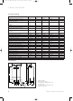
Table of contents 1 General information 1 1.1 1.2 1.3 1.4 1.5 General information . . . . . . . . . . . . . . . . . . For your information . . . . . . . . . . . . . . . . . . . . . Key to symbols . . . . . . . . . . . . . . . . . . . . . . . . . . Liability . . . . . . . . . . . . . . . . . . . . . . . . . . . . . . . . Specified use . . . . . . . . . . . . . . . . . . . . . . . . . . . EC designation . . . . . . . . . . . . . . . . . . . . . . . . . . 2 2 2 2 3 3 1 General information 2 2.1 2.2 2.3 2.
General information 1 Safety instructions 2 1.4 Specified use Vaillant ecoMAX appliances are made to fulfil the latest technical specifications and official safety regulations. These appliances are designed as boilers for use in central heating and hot water supply systems. If the appliances are used for purposes other than or in excess of these specifications, this shall be classed as incorrect operation, and neither the manufacturer nor supplier will accept any liability for resulting damage or injury.
3 Factory guarantee 4 Operation 3 Factory guarantee 4 Operation 3.1 Your guarantee Vaillant undertakes to rectify any manufacturing defect that occurs within twenty-four months of the installation date. 4.1 Overview 4.1.1 Operating controls 3.2 Registering with us Registration is simple. Just complete the Guarantee Registration Card and return to Vaillant within 30 days of installation. Your details will then be automatically registered within the Vaillant scheme.
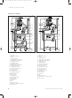
Operation 4 4.1.2 Advanced multifunctional system display 4.2 Initial checks before turning ON 4.2.1 Opening the service valves 1 2 3 4 1 2 1 0 3 bar Fig. B.3 Opening the service valves Fig. B.2 Advanced multifunctional system display The boiler system display (Fig. B.2) shows – during normal operation – current information on the heating system flow temperature (Fig. B.2. example gives flow temperature of 45 °C).
4 Operation 4.2.2 Checking the water contents 1 • Turn the main switch (2) to the “l” position. • The display will show the boiler flow temperature which indicates electrical power to the boiler. • The domestic hot water temperature can be adjusted using the hot water temperature control (3). • Turn the control clockwise to increase the temperature and anti-clockwise to decrease the temperature. 2 1 0 3 bar Note! This control adjusts the maximum domestic hot water temperature.
Operation 4 • The warmstart system is switched OFF by turning the hot water temperature control knob (1) anticlockwise to position c. The " " is NOT now illuminated. Reset the hot water temperature control knob to the desired setting, e.g. setting b Note! Irrespective of whether the warmstart facility is switched ON or OFF, the boiler will automatically operate to provide hot water whenever a hot water tap is opened. 4.
4 Operation 4.4.2 Setting the external controls 4.5 Status displays (Fig. B.10) (for maintenance and servicing work carried out by a qualified service engineer) 2 1 3 4 Fig. B.9 Setting the external controls • Set the room thermostat and/or the thermostatic radiator valves according to the instructions supplied with the control(s). Fig. B.
Operation 4 4.6 Resetting the appliance 1 max. 3 x ! STOP Attention! If the boiler still shuts off after a third attempt, then please consult your installer or Vaillant Service Solutions. The boiler also switches to “Fault” when there is not enough water in the system. This fault is indicated by fault code “F.22” “F.23” or “F.24”. The boiler can only be placed back in operation after the heating system has been properly refilled with water.
4 Operation 4.7 Turning the boiler OFF (ecoMAX 800 series only) 4.7.1 To turn OFF the central heating only (Summer mode) o C 4.7.2 To turn OFF central heating and hot water for short periods of time o C 2 1 Fig. B.13 Complete shutdown Fig. B.12 To turn OFF the central heating only (Summer mode) • Turn the main ON/OFF control (2) to the “0” position. • Turn the maximum radiator temperature control knob used to control the heating supply temperature (1) all the way to the left.
Operation 4 4.
834215_12 GB 08 2004 Subject to alteration