
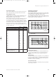
Technical data
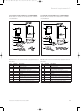

17
Boiler installation sequence 4
Instructions for installation and servicing ecoMAX 17
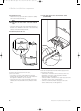
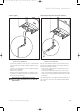
4.2 Rear flue exit
Mark the position of the air/flue duct and its circumfe-
rence.
4.3 Other flue options
Flue instructions for other flue systems such as vertical
RSF flues, flues run to the side of the boiler and the use
of additional bends etc. are detailed in the flue
installation instructions provided with the boiler.
Remove the template from the wall and plug the drilled
holes using the wallplugs supplied.
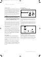
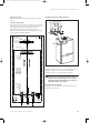
Fig. 4.2 Using Boiler template
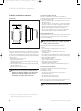
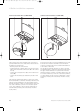
4.4 Fitting the boiler hanging bracket
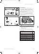
Fig. 4.3 Fitting the boiler
Fix the hanging bracket (2) to the wall using the screws
supplied. (it may be necessary to use additional or
alternative fixings to ensure adequate support).
Note:
If the boiler is to be fitted in a timber framed
building ensure that the bracket is secured to a
substantial part of the timber frame capable of
taking the weight of the boiler.
4.5 Install the flue system
Install the flue system (refer to separate air/flue duct
installation instructions)
85
50
240
75
75
23
50
3
1
2
Boiler casing
Minimum
Clearances
Reqd.
Flow
D.H.W.
out
Cold
Mains in
Gas in Return
Condensale
discharge
Minimum Clearances
Reqd.
Flue hole
(60/100 mm
flue system)
Fixing holes and
Position for
optional
pre-instalation
connection
Flue hole
(80/125 mm
flue system)
Please use
the new
Boiler hanging
bracket
ecoMAX 824/2
ecoMAX 828/2
ecoMAX 835
ecoMAX 613/2
ecoMAX 618/2
ecoMAX 622/2
ecoMAX 635
83 41 77_12 GB04.04.qxd 22.09.2004 12:34 Uhr Seite 17