
Technical data


41
Servicing 7
Instructions for installation and servicing ecoMAX 41
7. Servicing
7.1 Inspection and servicing
To ensure the continued safe and efficient operation of
the boiler it is recommended that it is checked and ser-
viced as necessary at regular intervals. The frequency of
servicing will depend upon the particular installation
conditions and usage, but in general the boiler should be
inspected once per year and serviced every second year.
We therefore recommend that a service contract be
taken out for the boiler. It is law that all servicing work is
carried out by a competent person (CORGI registered).
For safety reasons only genuine Vaillant spare parts
should be used when servicing the boiler.
Important
Failure to carry out work in accordance with
these instructions could result in personal
injury or damage to the property
7.2 Initial inspection
Every year the boiler should be inspected to check its
general condition. This inspection should include the boi-
ler, flue, pipework and electrical connections for any
indications of damage or deterioration. A gas rate check
of the boiler and a visual inspection of the combustion
should also be carried out.
Every second year the compact thermal module should
be removed and the burner and heat exchanger cleaned.
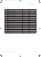
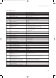
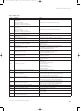
All inspection and servicing work should be performed in
the order as per Table 7.1
No Description Inspection Service
1 Carry out functional check of boiler X X
2 Remove the compact thermal module X
3 Clean primary heat exchanger X
4 Clean burner X
5 Refit compact thermal module,
replace burner seals
(Spare part number 98 1046) X
6 Check general condition of
boiler and clean as necessary X X
7 Check electrical plugs and connections X X
8 Check/re-pressurise expansion
vessel as necessary X
9 Check and clean condensate trap
and connection pipes X X
10 Check ignition and burner flame picture X X
11 Check boiler for any leaks X X
12 Check air/gas flue system X X
13 Complete benchmark logbook X X
Table 7.1
Note:
The boiler is fitted with a combustion analysis
test point. A suitable combustion analyser can
be connected to this point to establish the com-
bustion performance of the boiler.
It is not necessary to check the CO
2
content or
adjust the air ratio of the boiler during inspec-
tion or annual service.
This value requires checking and adjusting only
in the following instances: replacement of gas
valve, conversion to or from Natural Gas/ LPG
or if incorrect combustion is suspected.
Important
Before starting any maintenance work:
• Isolate the mains electricity supply by disconnecting
the plug at the socket outlet (if there is only an isola-
ting switch remove the fuse from the switch).
• Turn OFF the gas supply at the gas service valve fitted
to the boiler.
• When removing any water carrying components ensure
that water is kept away from all electrical components.
• Always use new seals and O–rings when replacing parts.
• Always test for gas soundness and always carry out
functional checks after any service work and after
exchanging any gas carrying component.
• Always check earth continuity, polarity and resistance
to earth with a multimeter after any service work and
after exchanging any electrical component.
Before commencing any servicing or maintenance work,
carry out an initial inspection of the system as follows:
• Inspect the flue, pipework and electrical connections
for indications of damage or deterioration.
• Inspect the air supply and ventilation arrangements of
the installation.
• Check the heating and water system, in particular the
condition of radiator valves, evidence of leakage from
the heating system and dripping hot water taps.
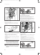
7.2.1 Removing the compact thermal module
Turn off the boiler
• Isolate the electrical supply to the boiler.
• Remove boiler bottom cover by releasing the two
spring retaining lugs and lowering the rear of the bot-
tom cover.
• Gently pull the bottom cover backwards to remove
from the appliance. Turn off the gas service valve.
• Turn off the boiler CH service valves.
• Loosen case retaining screw and release the front case
spring retaining clips located beneath the front edge
of the appliance.
• Remove the front casing by easing forward the bottom
edge and gently lifting.
• Lower electronic control box.
83 41 77_12 GB04.04.qxd 22.09.2004 12:34 Uhr Seite 41