
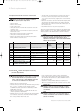
Technical data


52
9 Parts replacement
Instructions for installation and servicing ecoMAX52
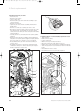
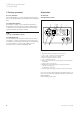
9.4 Replacement of gas valve
• Turn off boiler.
• Remove front casing.
• Lower control box.
• Remove burner, gas valve and fan assembly as pre-
viously detailed.
• Remove 4 screws (1).
• Separate gas valve and fan assembly from burner
manifold (2).
• Remove 2 screws (3) securing gas valve to fan.
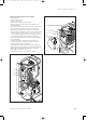
• Disconnect gas inlet supply connection from gas valve
by removing four screws. Refit the gas inlet supply
connection to the new gas valve using the new sealing
gasket supplied.
• Fit new gas valve to fan using the new sealing gasket
supplied.
• Refit gas valve and fan assembly to burner manifold
using the new sealing gasket supplied. Equally tighten
the four screws (1) to ensure a good seal is made.
• Reassemble burner, gas valve and fan assembly in
reverse order.
• Recommission boiler as previously detailed. Ensure
combustion analysis is carried out after part replace-
ment as detailed in section 9.8.
Fig. 9.2 Replacing the gas valve
Fig. 9.3 Gas valve
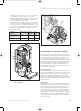
9.5 Replacement of central heating expansion vessel
• Turn off boiler.
• Remove front casing.
• Lower control box.
• Drain boiler as previously described.
• Disconnect union (1) from expansion vessel.
• Remove two screws (2) and remove retaining bracket (3).
• Slide the expansion vessel forward to remove from the
boiler.
• Reassemble in reverse order.
• Recommission boiler as previously detailed.
Fig. 9.4 Replacing the expansion tank
2
3
1
4
2
3
2
1
1
83 41 77_12 GB04.04.qxd 22.09.2004 12:34 Uhr Seite 52