
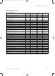
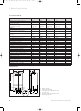
Technical data
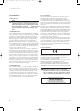
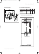
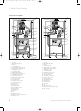
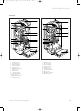

2.2 Dimensions
Fig. 2.1
2 Hanging bracket
3 Heating–system return
4 Cold–water inlet (ecoMAX 800/2 only)
5 Gas connection
6 Hot–water outlet (ecoMAX 800/2 only)
7 Heating–system flow
70
190
480
800
2
100
380*
7
Ø 20
100 100
Ø 20
5
3
7
Ø 20
20
R 1
/2
180
4
6
*(ecoMAX 635, 835: 450)
6
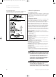
2 Boiler Specification
Instructions for installation and servicing ecoMAX6
2.1 Technical data (2)
ecoMAX 613/2 E 618/2 E 622/2 E 635 E Units
Maximum CH heat input (G 20) (net) 13.5 18.4 22.4 34.9 kW
Maximum CH heat input (G 31) (net) 13.5 18.4 22.4 34.9 kW
CH heat output range
80 °C flow/60 °C return 4.6 – 13.5 11.0 – 18.4 13.4 – 22.4 10.5 - 34.9 kW
50 °C flow/30 °C return 4.8 – 14.2 11.6 – 19.4 14.1 – 23.6 11.0 - 36.7 kW
SEDBUK A A A A Band
SAP Seasonal Efficiency 91.2 91.2 91.2 91.2 %
Inlet gas working pressure required
(natural gas) 20 20 20 20 mbar
Inlet gas working pressure required
(Propane) 37 37 37 37 mbar
Gas supply (G20) Gross CV (s.t.) 37.8 37.8 37.8 37.8 MJ/m
3
Gas supply (G31) Gross CV (s.t.) 95.65 95.65 95.65 95.65 MJ/m
3
Gas rate (natural gas) max. 1.43 1.95 2.37 3.7 m3/h
Gas rate (Propane) max. 1.05 1.43 1.74 2.7 kg/h
CH temperature flow range 30 – 85 30 – 85 30 – 85 30 - 85 °C
Minimum CH water flow (for 20 °C rise) 580 790 960 1480 l/h
Pump pressure available 0.25 0.25 0.25 0.25 bar
10l expansion vessel pre–charge pressure 0.75 0.75 0.75 0.75 bar
Maximum CH system pressure 2.5 2.5 2.5 2.5 bar
Connections heating flow/return 22 22 22 22 mm
Gas inlet 15 15 15 15 mm
Pressure relief discharge pipework (min.) 15 15 15 15 mm
Condensate drain (min. internal drain) 19 19 19 19 mm
Weight 39 39 40 41 kg
Primary water content 1.8 1.8 2.0 2,2 l
Volume of condensate (max.) 1.2 2.1 2.5 3,3 l/h
Maximum flue gas temperature 70 70 70 70 °C
Electrical supply voltage 230/50 230/50 230/50 230/50 V ~/Hz
Internal fuse (slow) main voltage 4 4 4 4 A
Internal fuse (slow) low voltage 4 4 4 4 A
Power input 115 115 115 115 W
83 41 77_12 GB04.04.qxd 22.09.2004 12:34 Uhr Seite 6