
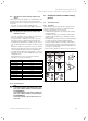
Specifications

36 Instructions for installation and servicing ecoTEC
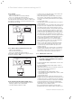
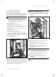
6.1.2 Heating
• Switch on the appliance.
• Make sure that there is a heating demand.
• Press “i” to activate the status indicator.
As soon as a heat demand is received, the appliance
runs through the status indicators “S. 1” to “S. 3”, until
the appliance is running correctly in normal mode and
the display shows “S. 4”.
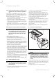
plus pro
Fig. 6.2 Display indicator during heating mode
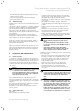
6.1.3 Water heating (combination boilers only)
• Switch on the appliance.
• Fully open the hot water tap.
• Press “i” to activate the status indicator.
If the water heating is working correctly, the display
shows the following: “S.14”.
plus pro
Fig. 6.3 Display indicator during water heating
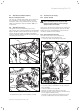
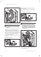
6.1.4 Final flush of the heating system (“hot”)
• Operate the appliance until the appliance and the
heating system are up to temperature.
• Check the heating system for leaks.
• Connect a hose to the drain valve located at the low-
est position of the heating system.
• Shut off the appliance, open the drain valve and all
bleed valves on the radiators and allow the water to
flow out of the heating system and the boiler quickly
and fully.
• Close the drain valve.
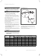
• Fill the heating system again with water as described
in Section 5.4.4.
• Release water from the system until the system design
pressure of 1.0 bar is attained. (The actual reading on
the digital pressure gauge should ideally be 0.5 bar
plus an additional pressure corresponding to the high-
est point of the system above the base of the boiler –
10 m head equals an additional 1 bar reading on the
pressure gauge. The minimum pressure should not be
less than 1 bar in any installation.) If the system is to
be treated with an inhibitor it should be applied at this
stage in accordance with the manufacturer’s instruc-
tions. Further information can be obtained from
Sentinel, Betz Dearborn Ltd., Tel: 0151 420 9595, or
Fernox, Alpha–Fry technologies. Tel: 0870 8700362.
• Refit the boiler casing (see section 5.10).
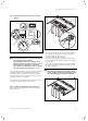
• Only in ecoTEC plus appliances: Attach the bottom
cover to the boiler by sliding the front edge of the
cover into the lip at the bottom front edge of the
appliance chassis.
• Carefully push the rear of the bottom cover upwards
until the spring retaining clips engage at the side of
the appliance. It may be necessary to adapt the bot-
tom cover by removing the easy break sections.
6.2 Handing over to the user
Note
When you have finished the installation, attach
the sticker supplied (835593) to the appliance
in the user’s language.
• Set the maximum radiator temperature control to the
desired setting.
• Set the maximum hot water temperature control to
the desired setting.
• Instruct the user in the safe and efficient operation of
the boiler, in particular the function of
– the boiler on/off control
– the maximum radiator temperature control
– the maximum hot water temperature control (combi-
nation boilers only)
– the pressure gauge
• Show the user how to operate any external controls.
• Explain to the user the importance of having the boiler
regularly serviced by a competent servicing company.
To ensure regular servicing, it is strongly recommend-
ed that arrangements are made for a Maintenance
Agreement. Please contact Vaillant Service Solutions
(0870 6060 777) for further details.
• Record central heating operating pressure in the
Benchmark gas boiler commissioning checklist along
6 Functional checks (commissioning part II)