Installation Instructions GB Unvented hot water storage cylinders for use with Vaillant boilers Vaillant Vantage 120 Vaillant Vantage 150 Vaillant Vantage 200 2140100 ETC 00394 9411064
Contents Page 1 Description . . . . . . . . . . . . . . . . . . . . . . . . . 2 2 Technical data . . . . . . . . . . . . . . . . . . . . . . 5 3 Dimensions . . . . . . . . . . . . . . . . . . . . . . . . . 7 4 Applications . . . . . . . . . . . . . . . . . . . . . . . . 10 5 Functional diagrams . . . . . . . . . . . . . . . . . . 11 5.1 5.2 11 Functional diagram of the primary circuit . . . . Functional diagram of the secondary connections . . . . . . . . . . . . . . . . . . . . . . . . . . . .
Description 1 1 Description The VANTAGE range of unvented hot water storage cylinders are indirectly heated cylinders which are designed for use with Vaillant gas boilers only. The VANTAGE must NOT be installed with boilers supplied by any other manufacturer. VANTAGE cylinders are available in three sizes of 120, 150 and 200 litre nominal capacity. The cylinders are of glass lined steel construction, insulated with CFC free foam and enclosed in a decorative sheet metal casing.
1 Description Note To Installers This product has been assessed and found to comply with the requirements of the Building Regulations for unvented hot water storage systems and must not be altered or modified in any way. The installation must be carried out by a competent person and be in accordance with the relevant requirements of the Local Authority, Building Regulations, Building Standards (Scotland) Regulations and the byelaws of the local Water Undertaking.
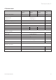
Technical data 2 2 Technical data Nominal storage capacity Vantage 120 Vantage 150 Vantage 200 Unit 120 150 200 litres Nominal DHW flow from VANTAGE 120/150 15 l/min @ 60 °C VANTAGE 200 20 l/min @ 60 °C Maximum water supply pressure 10 bar Maximum primary circuit pressure 2.5 bar Expansion vessel charge pressure 4 bar Operating pressure 3.5 bar Net weight 70 82 101 kg Weight (full) 190 232 301 kg Cylinder connections: Cold mains inlet 22 mm compression D.H.W.
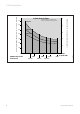
Vantage 200 60 50 40 50 Vantage 150 40 Vantage 120 30 30 20 20 10 10 8 THERMOcompact boiler ecoMAX boiler 6 Note: Times shown for Vaillant boilers assume no simultaneous heating demand 70 10 12 14 16 18 615 E 613/2 E 20 22 620 E 618/2 E 24 624 E 622/2 E 26 28 Heat input to cylinder (kW) 628 E VIH 380/2 Cylinder Heat Up Times Reheat time for 70 % of cylinder contents (minutes) Approximate cylinder heat up time - 15 °C to 65 °C (minutes) 2 Technical data Vaillant Vantage 120/
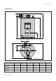
Dimensions 3 b f c a 70 103 3 Dimensions 120 VIH 382/3 (Redesign) e d 170 127 Fig.
3 Dimensions Boiler fitted directly above the cylinder VIH 378/3 (Redesign) A B C D Fig.
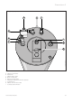
Dimensions 3 Vantage 120, 150, 200 A H C B F E I D VIH 360/0 (Redesign) G Fig.
4 Applications 4 Applications The Vaillant VANTAGE may only be connected to a Vaillant boiler. No other indirect heat source may be used. The following Vaillant boilers are available for use with the VANTAGE cylinders: THERMOcompact system boilers 615 E (VU 152-5) 620 E (VU 202-5) 624 E (VU 242-5) 628 E (VU 282-5) ecoMAX - Condensing system boilers 613/2 E (VU 126) 618/2 E (VU 196) 622/2 E (VU 246) 4.
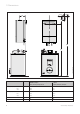
Functional diagrams 5 5 Functional diagrams 5.1 Functional diagram of the primary circuit 1 3 A B 4 2 D 5 VIH 362/2 C Fig.
5 Functional diagrams 5.2 Functional diagram of the secondary connections 5 B 1 3 A C 6 2 E D VIH 363/2 4 Fig.
Functional description 6 6 Functional description 6.1 D.H.W. Temperature Control The VANTAGE is supplied fitted with a user adjustable domestic hot water (DHW) thermostat and also a 3 port mid position diverter valve. 6.2 C.H. Control Central heating is controlled by the fitted 3 port mid position diverter valve in conjunction with suitable external controls, such as a programmer, room thermostat or thermostatic radiator valves.
6 Functional description 6.4 Secondary System The VANTAGE is provided with all necessary safety and control devices for unvented DHW operation. These are as follows: A A prefitted temperature and pressure relief valve (90 °C, 7 bar) (An additional overheat thermostat is contained within the Vaillant boiler). B Expansion relief valve (6.0 bar) incorporating a non return valve. C Pressure limiting valve (3.5 bar) incorporating a line strainer.
Installation requirements 7 7 Installation requirements 7.1 Siting Locate the VANTAGE in the building in the most convenient position ensuring that: – The discharge pipe from the tundish can be installed with a minimum fall of 1:200 and can be terminated in a safe and visible position (see section 7.5 Discharge pipework). – The base chosen for the unit is level and capable of supporting the weight of the cylinder when full (see section 2: Technical Data). – The installation site is frost-free.
7 Installation requirements 7.2 Mains Water Pressure The DHW performance of an unvented cylinder installation will correspond to the available mains water supply pressure and flow rate. To achieve optimum performance from the VANTAGE a suitable cold mains water supply must be available, i. e. the measured static pressure from the incoming mains water supply should be at least 2.0 bar. A corresponding flow rate at least 20-25 l/min should be available.
Installation requirements 7 7.3 Secondary System To achieve optimum distribution of the water supply it is important that the water system pipework and terminal fittings are correctly sized and balanced. The teed-off supply to the bath outlet should be in 15 mm pipework. The tee-offs to sinks and basins should be in 10 mm pipework. Terminal fittings should be suitable for mains pressure operation and taps should be of the aerated type to prevent splashing. Flow rates from VANTAGE, hot 60 °C.
7 Installation requirements 7.4 Pipework – Primary Circuit The primary circuit pipework between the Vaillant boiler and the VANTAGE should be installed using copper tube of minimum size 22 mm. If the distance between the boiler and the cylinder is excessive, a larger pipe diameter may be necessary. It is not necessary to install a circulating pump in this pipework because all Vaillant wall mounted boilers contain a built-in circulating pump.
Installation requirements 7 7.5 Discharge Pipework The outlet connections of both the temperature and pressure relief valve and expansion relief valve should be connected in 15 mm copper tube to the tundish supplied. The tundish should be installed vertically, as close to the VANTAGE as possible and within 500 mm of the temperature and pressure relief and expansion relief valve outlets. It must be positioned away from any electrical components and installed in the same space as the VANTAGE cylinder.
7 Installation requirements Typical discharge pipe arrangement metal discharge pipe from temperature relief valve to tundish safety device (e.g. temperature relief valve) 500 mm maximum tundish Discharge below fixed grating 300 mm minimum metal discharge pipe from tundish with continuous fall. See 7.5 Table 4 and worked example fixed grating VIH 365/1 trapped gully Under fault conditions, the discharge warning pipe can emit water at near boiling temperature.
Installation procedure 8 8 Installation procedure • Unpack the VANTAGE cylinder and check the contents (detailed in section 1: notes to installers). • Position the VANTAGE in accordance with section 7.1: Siting W M H ´A´ Port heating flow ´AB´ Port boiler flow Fig. 9 VIH 366/1 ´B´ Port to cylinder Note: For VANTAGE 150 and 200 cylinders, remove the blanking plug from the DHW thermostat pocket located centrally at the top of the cylinder.
8 Installation procedure 8.2 Secondary system Pipework • Connect the two cold water control valves together as shown in fig 11., ensuring that the orientation of the valves, when installed in the cold mains supply, allows the 15 mm outlet of the expansion relief valve to be connected to the tundish.
Installation procedure 8 • Connect the expansion vessel to the installed water controls by either: i. Screwing the vessel directly into the control assembly at the purpose provided connection (3, fig. 11) or, ii. Connecting the vessel to the control assembly via copper pipe or a suitable approved flexible connection hose, ensuring that the vessel is adequately supported. Note: An optional ”Remote Expansion Vessel Mounting Kit” (Art no. 2378083) is available for use with VANTAGE cylinders.
8 Installation procedure VANTAGE 120, 150 and 200 installation D C J B A H K L F I E VIH 374/0 (Redesign) G Fig.
Installation procedure 8 8.4 Electrical connections and controls Immersion heater electrical connections 8.4.1 Immersion Heater Warning: The immersion heater must be earthed. Install a separate electrical supply to the immersion heater in accordance with the current IEE wiring regulations (BS 7671). The immersion heater must be wired in 2.5 mm2 heat-resisting cable from a double pole isolating switch. The circuit must be protected by a 13 amp fuse.
8 Installation procedure 8.4.3 Control options – system wiring scheme Important 1-10 must go to the corresponding number in the wiring centre. Connection details for control systems utilising 3 port motorised valve via external wiring centre/junction box Diagram only applies to the specific controls mentioned 3 amp fused main supply THERMOcompact 600 series ECOmax 600/2 series terminal strip L N L N 3 4 5 L N L N 3 4 5 Programmer for programmer connections see fig.
Installation procedure 8 Connection details between programmer and wiring centre.
9 Commissioning 9 Commissioning 9.1 Filling Secondary D.H.W. Circuit Note: Do not manually open the temperature and pressure relief valve or expansion relief valve for venting purposes (any foreign matter in the pipework may cause damage to the valve seats). • Ensure that the cylinder drain valve (E, fig. 6) is clo• • • sed. Open all the hot and cold water taps or other terminal fittings.
Commissioning 9 9.2 Filling the Primary Circuit Note: Do not use boiler pressure relief valve for venting purposes. • The complete primary C.H. system must be flushed • • • • • out with both cold and hot water. Fill and vent the central heating system as detailed in the boiler installation instructions. To assist with this operation set the manual override lever on the 3 port diverter valve (fig. 9) to the MANUAL position, and lock in this position by pushing the lever into the valve head.
9 Commissioning 9.4 User’s Instructions Hand the instructions for use to the user for retention and instruct in the safe operation of the boiler and cylinder. Advise the user of the operation of the cylinder thermostat, and that normally a setting of 5-6, which gives a stored water temperature of approximately 60 °C is adequate. Note: In hard water areas the DHW temperature setting should not exceed this setting to avoid possible scale build-up.
Maintenance 10 10 Maintenance The following maintenance work has to be carried out annually by the competent installer or Vaillant Service Solutions. • Inspection of pressure/temperature relief valve and • • • • expansion relief valve. Manually operate each valve by twisting the operating cap, and check if water flows unobstructed via the tundish to the discharge point. Ensure that both valves re-seat satisfactorily. Check pressure of expansion vessel.
11 Fault finding 11 Fault finding Note: Only genuine spare parts supplied by Vaillant Limited must be used. Fault A: The water from the cylinder is cold. Does boiler operate? NO Do external controls function? YES Remedy fault according to boiler instructions. NO Remedy fault according to controls instructions. YES Is 3-port valve in corect position? (Mid or DHW position). Does cylinder thermostat operate? NO Replace cylinder thermostat. YES Check/replace 3-port valve.
Fault finding 11 Fault B: Water discharging from expansion relief valve. Manually reset / seat expansion relief valve. Is discharge still occuring? NO YES Is the discharge occuring only when the cylinder is being heated? NO YES Check pressure charge in expansion vessel. NOT OK Reset pressure in expansion vessel. Does pressure hold? Turn off boiler and immersion heater. Is discharge still occuring? YES OK Exchange expansion relief valve.
11 Fault finding Fault C: Water discharging from temperature/ pressure relief valve (TPRV). Manually reset the TPRV. Is discharge still occuring? NO YES YES Check temperature control of boiler. Is discharge occuring only when the boiler is in use? OK NO Is discharge occuring only when the immersion heater is in use? Does 3-port valve change to heating position when cylinder reaches temperature? YES NO Check operation of cylinder thermostat. YES Replace TPRV.
Fault finding 11 Fault D: Deteriorating water pressure and flow from hot water terminal fittings. Check incoming main water pressure. Poor Inform customer to have water service checked by water undertaker. Dirty Clean / replace strainer. Faulty Replace faulty valve. OK Check line strainer (in pressure limiting valve). OK Check pressure limiting valve. OK Check sytem for blockage. Blocked Replace / clear blocked components. OK Symptoms still persisting? YES NO Fault remedied.
83 39 21 GB01 • 12/2001 V • Subject to alteration • Printed in Germany Head Office Vaillant Ltd.
INSTRUCTIONS FOR USE VAILLANT VANTAGE UNVENTED HOT WATER CYLINDER 120 / 150 / 200
INTRODUCTION Your Vaillant VANTAGE unvented hot water cylinder and Vaillant boiler, together provide you with a modern, efficient, high performance heating and hot water system. Because your VANTAGE hot water cylinder is supplied with water directly from the mains, you get the benefit of mains pressure hot water at your hot taps, without the need for storage tanks in the loft and without a hot water pump. The VANTAGE is made from high quality glass lined steel within an easy clean casing.
How to use your VANTAGE hot water cylinder Domestic hot water thermostat 6 78 Fig. 1 VIH 376/1 5 1 2 3 4 Your Vaillant boiler and VANTAGE unvented hot water cylinder will provide both central heating and mains pressure hot water. If a programmer has been fitted to control the central heating and hot water, check that this is set to the desired on and off periods. Check that the Vaillant boiler is operational as detailed in the Instructions for use supplied with the boiler.
1 Domestic hot water thermostat. 2 Immersion heater flange cover. 3 Cylinder drain point. 1 3 Fig. 2 4 VIH 377/1 (Redesign) 2 Fig.
IMPORTANT NOTES Shutting down the VANTAGE cylinder Care and Maintenance To shut down the heating and hot water system for short periods, simply turn off the Vaillant boiler as shown in the instructions supplied with the boiler. The casing of the VANTAGE cylinder may be cleaned with a damp cloth and a little soap. Do not use any abrasive or solvent material which could damage the case or fittings.
Sales 01634 292310 Service Solutions 0870 6060 777 Technical Advice 01634 292392 Training 01634 292370 834032GB· 01/2000 V · GW-D · Subject to alteration Head Office Vaillant Ltd.
VAILLANT SPARE PART CATALOGUE Vaillant unvented indirect hot water cylinder VANTAGE VIHC120 VANTAGE 120 VANTAGE 150, 200 Vaillant gas fired storage water heater VGH 130/1, 160/1, 190/1 VGH 130/2, 160/2, 190/2 VGH 130/3, 160/3, 190/3, 220/3 8026 97 GB 09/96
View of appliances Content Page Vaillant gas fired storage water heater VGH 130/1, 160/1, 190/1 Vantage VIHC 120 VGH 130/2 Z, 160/2 Z, 190/2 Z Vantage 120, 150, 200 3 - 11 Vaillant unvented indirect hot water cylinder 13 - 25 Vaillant safety assembly 27 - 31 VGH 130/3 Z - 220/3 Z Subject to alteration 1
Vaillant gas fired storage water heater Page Vaillant gas fired storage water heater VGH 130/1, 160/1, 190/1 4-5 Vaillant gas fired storage water heater VGH 130/2 Z, 160/2 Z, 190/2 Z 6-7 Vaillant gas fired storage water heater VGH 130/3 Z, 160/3 Z, 190/3 Z, 220/3 Z Subject to alteration 8 - 11 3
Vaillant gas fired storage water heater VGH 130/1, 160/1, 190/1 4 Subject to alteration
Vaillant gas fired storage water heater VGH 130/1, 160/1, 190/1 Pict. No. Article-No.
Vaillant gas fired storage water heater VGH 130/2 Z, 160/2 Z, 190/2 Z 6 Subject to alteration
Vaillant gas fired storage water heater VGH 130/2 Z, 160/2 Z, 190/2 Z Pict. No. Article-No.
Vaillant gas fired storage water heater VGH 130/3 Z, 160/3 Z, 190/3 Z, 220/3 Z 8 Subject to alteration
Vaillant gas fired storage water heater VGH 130/3 Z, 160/3 Z, 190/3 Z, 220/3 Z Pict. No. Article-No.
Vaillant gas fired storage water heater VGH 130/3 Z, 160/3 Z, 190/3 Z, 220/3 Z 10 Subject to alteration
Vaillant gas fired storage water heater VGH 130/3 Z, 160/3 Z, 190/3 Z, 220/3 Z Pict. No. Article-No. 28 04-2882 04-2881 04-3951 17-1174 07-2355 08-8624 07-1880 07-1880 07-1899 13-9419 98-0936 08-9317 08-9323 28-4049 11-6480 20-3841 07-6228 29 30 31 32 33 35 36 37 38 39 40 41 Subject to alteration Part Indic.
Vaillant unvented indirect hot water cylinder Page Vaillant unvented indirect hot water cylinder VANTAGE VIHC 120 14 - 15 Vaillant unvented indirect hot water cylinder VANTAGE VIHC 120 Control panel 16 - 17 Vaillant unvented indirect hot water cylinder VANTAGE VIHC 120 Component and connection details 18 - 19 Vaillant unvented indirect hot water cylinder VANTAGE VIHC 120 Flange assembly, hot water outlet 20 - 21 Vaillant unvented indirect hot water cylinder VANTAGE 120 22 - 23 Vaillant unvented i
Vaillant unvented indirect hot water cylinder VANTAGE VIHC 120 14 Subject to alteration
Vaillant unvented indirect hot water cylinder VANTAGE VIHC 120 Pict. No. Article-No. 1 2 3 4 5 6 7 8 9 10 11 12 13 14 15 45-9886 08-2205 28-5847 98-0910 11-6480 28-4049 08-0408 17-7507 16-0029 08-5114 98-0325 06-0051 08-5014 05-0714 25-5008 25-5018 16-3489 25-5907 16 17 Subject to alteration Part adjusting screw drain valve protection anode flange gasket screw disc flow tee piece air vent sleeve nut union connection sealing ring air vent connector 3 port valve motor motor elbow cable tree Indic.
Vaillant unvented indirect hot water cylinder VANTAGE VIHC 120 Control panel 16 Subject to alteration
Vaillant unvented indirect hot water cylinder VANTAGE VIHC 120 Control panel Pict. No. Article-No. 4 5 6 7 8 9 10 11 12 13 14 15 16 17 18 19 06-0018 13-0327 23-5748 07-5485 10-1804 10-1534 14-3950 25-1777 20-1623 25-0763 25-0762 25-5908 08-4471 25-2780 25-0790 12-0065 Subject to alteration Part Indic.
Vaillant unvented indirect hot water cylinder VANTAGE VIHC 120 Component and connection details 18 Subject to alteration
Vaillant unvented indirect hot water cylinder VANTAGE VIHC 120 Component and connection details Pict. No. Article-No. 5 2378096 2378096 2370033 cu75 control valve type A cu75 control valve type B discharge pipework type A discharge pipework type B 14 12370051 06-4505 2370009 2370010 2370013 2370016 2370015 expansion vessel immersion heater elbow adaptor expansion valve expansion valve temperature and pressure relief valve 15 2370011 line strainer 7 8 9 10 13 Subject to alteration Part Indic.
Vaillant unvented indirect hot water cylinder VANTAGE VIHC 120 Flange assembly, hot water outlet 20 Subject to alteration
Vaillant unvented indirect hot water cylinder VANTAGE VIHC 120 Flange assembly, hot water outlet Pict. No. Article-No.
Vaillant unvented indirect hot water cylinder VANTAGE 120 22 Subject to alteration
Vaillant unvented indirect hot water cylinder VANTAGE 120 Pict. No. Article-No.
Vaillant unvented indirect hot water cylinder VANTAGE 150, 200 24 Subject to alteration
Vaillant unvented indirect hot water cylinder VANTAGE 150, 200 Pict. No. Article-No.
Vaillant safety assembly Page Vaillant hot water storage heater Safety assembly acc.-no. 695, 696 28 - 29 Vaillant hot water storage heater Safety assembly acc.-no.
Vaillant hot water storage heater Safety assembly acc.-no.
Vaillant hot water storage heater Safety assembly acc.-no. 695, 696 Pict. No. Article-No. 1 2 3 4 5 6 7 8 19-0707 11-1369 98-0438 08-1625 98-0151 14-9104 13-7508 Part safety assembly, cpl. safety valve sleeve nut packingring connection piece packingring pressure reducing valve tundish Indic. Type, Remarks see acc.-no. 660, 661 in valid appliance list 6 bar with parts 3, 4 Notice acc.-no. 660 for pressure under 6 Bar acc.-no.
Vaillant hot water storage heater Safety assembly acc.-no.
Vaillant hot water storage heater Safety assembly acc.-no. 660, 661 Pict. No. Article-No. 1 2 3 4 5 6 7 8 9 10 11 13 14 15 16 08-1625 98-0197 98-0223 01-0050 13-7508 13-7291 98-1605 95-0057 14-3981 13-7298 19-0709 19-0707 11-1228 11-1369 98-0438 13-7513 14-9106 - 17 18 19 20 Subject to alteration Part safety assembly, cpl.