To be left with the user Instructions for Use, Installation and Servicing ecoMAX pro GB Wall hung condensing boilers for traditional open vented systems 18 E 28 E
Table of Contents Page 1 List of Contents . . . . . . . . . . . . . . . . . . . . . . . . . 1.1 Contents included with ecoMAX pro boiler . . . 4 4 2 Introduction . . . . . . . . . . . . . . . . . . . . . . . . . . . . 2.1 General Information . . . . . . . . . . . . . . . . . . . . . 2.2 Gas Category . . . . . . . . . . . . . . . . . . . . . . . . . . . 2.3 Gas Safety (Installation and Use) Regulations 2.4 Gas Testing and Certification . . . . . . . . . . . . . . 2.5 CE Mark . . . . . . . . . . . . . . .
Table of Contents Page 15 Servicing . . . . . . . . . . . . . . . . . . . . . . . . . . . . . . 15.1 General . . . . . . . . . . . . . . . . . . . . . . . . . . . . . . . . 15.2 Spark Electrode . . . . . . . . . . . . . . . . . . . . . . . . . 15.3 Burner . . . . . . . . . . . . . . . . . . . . . . . . . . . . . . . . . 15.4 Combustion Chamber and Heat Exchanger. . . 15.5 Inner Casing Panel Seal Check . . . . . . . . . . . . . 24 24 24 25 26 26 16 Combustion analysis . . . . . . . . . . . . . . . . . . .
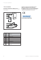
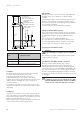
1 List of contents 1 List of contents 1.1 Contents included with ecoMAX pro boiler Ensure that all contents are included before commencing installation. Vaillant Ltd. support the Benchmark initiative. Within the information pack you will find a Benchmark Log Book. It is very important that this is completed correctly at the time of installation, commissioning and handover to the user. 1 2 3 4 5 6 9 7 8 Fig. 1.
Important information 2 2 Introduction 2.1 General Information Thank you for choosing a Vaillant boiler. The information given in this booklet will enable you to obtain the best performance from your boiler. The Benchmark logbook should be completed by the installer and/or commissioning engineer and handed to the user. Note! This boiler must be installed and serviced by a competent person in accordance with the Gas Safety (Installation and Use) Regulations 1998.
2 Important information Sheet Metal Parts This boiler contains metal parts (components) and care should be taken when handling and cleaning, with particular regard to edges. 2.12 Boiler Casing Do not remove or adjust the casing in any way, as incorrect fitting may result in incorrect operation or failure to operate at all. Sealed Components Under no circumstances must the User interfere with any sealed component as this could result in a potentially dangerous situation arising. 2.
2 Important information 2.17 Guarantee Our confidence in the quality of craftmanship and performance of our products is demonstrated by the Vaillant two year guarantee. During the first year from installation the guarantee covers your boiler against manufacturing defects for both parts and labour. In order to extend this guarantee to the second year from installation all you have to do is ensure that your boiler receives a service when it is a year old.
4 General Information 4 General Information Important notice The boiler is supplied in one pack and the flue is supplied separately. This boiler is factory set for use on Natural Gas (G20), ecoMAX pro 28E only can be field adjusted for use on LPG (propane G31). Where no British Standards exists, materials and equipment should be fit for their purpose and of suitable quality and workmanship. Refer to Manual Handling Operations, 1992 regulations.
4 General Information 4.7 Heating System Controls It is recommended that a programmer and room thermostat control the boiler. Thermostatic radiator valves may be installed, however they must not be fitted in a room where the room thermostat is located. Note! All systems must have at least one radiator not fitted with a thermostatic valve. Note! For further information, see the current issue of the Building Regulations, approved document L1, and the references: 5.
Water system 5 450mm MIN. HEIGHT Open (vented) system. Recommended relationship between pump, cold feed and vent. 22mm (MIN.) VENT FEED AND EXPANSION CISTERN 15mm (MIN) COLD FEED PUMP BOILER HEATING CYLINDER 1000mm MIN. FLOW RETURN 15mm (MIN.) BY-PASS (if required) 5.5 Inhibitor Attention is drawn to the current issue of BS 5449 and BS 7593 on the use of inhibitors in central heating systems.
Water system 5 5.9 Sealed water Systems The installation must comply with the appropriate requirements of the current issue of BS4814, BS5449, BS6759, BS6798 and BS7074 Part 1 and 2. For IE your attention is drawn to the current edition of IS 813. See Fig. 5.4 for a suggested layout. 3 LITRES (0.
6 Boiler Location and Ventilation 6 Boiler Location and Ventilation 6.1 Boiler Location The boiler may be installed in any room although particular attention is drawn to the requirements of the current issue of BS7671, IEE Wiring Regulations, the electrical provisions of the Building Regulations (Scotland), and in IE the current edition of IS 813 and the ETCI rules, with respect to the installation of a boiler in a room containing a bath or a shower.
Flue 7 7 Flue 7.1 Flue Position and Length The standard horizontal flue is fitted onto the top of the boiler. See Fig. 7.1 and 7.2 to determine whether a standard flue can be used. WALL THICKNESS 'X' = 75 TO 550 mm "X" 7.2 Flue termination The following details refer to both flue systems. a. The terminal must be positioned such that the products of combustion can disperse freely at all times. b. In certain weather conditions a plume of water vapour may be visible from the flue terminal.
7 Flue Installation Preparation 8 Terminal position mm A1) Directly below an opening, above an opening or horizontal to an opening i.e.
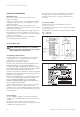
8 Installation Preparation Boiler fixing 9 3°±1° 176 RETAINING LUGS 900 Ø 127 INNER CASING PANEL WALL TEMPLATE Fig. 8.3 To allow for the flue passing through the wall at this angle a 127 mm hole should be drilled irrespective of internal or external installation. If necessary remove the template whilst drilling the flue hole. Fig. 8.2 9 Boiler fixing 8.3 Rear flue exit Mark the position of the air/flue duct and its circumference. 9.
10 Gas, Water and Condensate Connections 10 Gas, Water and Condensate Connections 10.1 Gas Connection Before connection check the supply of local gas. The gas supply can be connected from below, or through the wall at the rear of the boiler. Ensure the supply pipe is fully engaged in the compression fitting on the gas service valve inlet. See Fig. 10.1. and refer to section 4.3.
Flue Preparation and Installation 11 11 Flue Preparation and Installation 11.1 Flue Length All dimensions are in mm. To determine flue length, temporarily fit flue elbow to top of boiler. For rear or side flue, measure the distance from the outside wall to the butt joint of the flue elbow fitted on top of the boiler. A standard flue system will be suitable if the length measured ‘Y’ is less than 633 mm, see Figs. 11.1 and 11.2.
11 Flue Preparation and Installation Y X EXTENDED HORIZONTAL FLUE X + Y must not exceed 10 metres plus standard horizontal flue kit. Reduce flue length by 1 metre for every additional 90° or pair of 45° bends. Total flue length must not exceed 10 metres plus standard horizontal flue kit Reduce flue length by 1 metre for every additional 90° or pair of 45° bends. Fig. 11.4 Elevated horizontal flue 11.3 Flue Assembly The flue assembly is a push fit design with securing collars.
Electrical Connections 12 12 Electrical Connections Warning! This boiler must be earthed. Connect both the mains supply and switched live from the external controls (room thermostat and, if applicable, frost thermostat) into the marked terminals as shown in Figs. 12.2 and 15.1. switched live switched live All system components must be of an approved type, and meet the requirements of the current IEE Wiring Regulations, and in IE the current edition of the ETCI rules.
13 Commissioning 13 Commissioning Note! During commissioning the overheat thermostat may trip before air is completely removed from the system. If this occurs the boiler can be reset by pushing the manual reset button on the overheat thermostat (see Fig. 13.1). 13.1 Preliminaries - All Systems A competent person should carry out commissioning, in accordance with the current issue of BS 6798.
Commissioning 13 The boiler will then continue to fire until the user controls are satisfied. Note: After the first power up the firing sequence changes. After one minute stabilisation time the boiler will ramp slowly to full rate rather than going immediately to full rate, this feature is designed to cope with small system requirements. 13.
14 Conversion 14 Natural Gas to LPG conversion (ecoMAX pro 28E only) - Press the ‘-‘ key and scroll through until ‘96’ (installer mode) is shown on the screen, then press the ‘mode’button again. The ecoMAX pro 28E is able to be field adjusted for use on LPG – propane G31 gas. To enable conversion the use of a combustion analyser is necessary.
Conversion 14 "A" throttle – "Pmax" rotate to increase "B" offset adjustment "Pmin" rotate to increase Fig. 14.4 - Again in screen ‘8’, Set the appliance fan speed/burner to minimum by pressing the ‘-‘ key until ‘1’ (burner to Pmin) is shown on the right hand side of the screen. Press the ‘mode’ button again. Fig. 14.5 - Check the CO2 value, which should be 10.5 % ± 0.2 %. If adjustment proves necessary then proceed as follows.
15 Servicing 15 Servicing 15.1 General To ensure the continued safe and efficient operation of the boiler it is recommended that it is checked and serviced as necessary at regular intervals. The frequency of servicing will depend upon the particular installation conditions and usage, but in general once per year should be adequate. It is law that all servicing is carried out by a competent person (CORGI registered).
Servicing 15 15.3 Burner Refer to Figs. 15.2, 15.3, 15.4 and 15.5. Isolate the gas supply at the gas service cock. Disconnect the gas supply at the union nut of the gas service cock. FLUE ADAPTER COMBUSTION ANALYSER TEST POINT Note! Do not disconnect at the gas valve. Remove the two gas pipe bracket securing screws from underside of inner case, see Fig. 15.2. Drop down the control panel into the service position. Remove the four screws from the chassis front, see Fig. 15.3.
15 Servicing 15.4 Combustion Chamber and Heat Exchanger Refer to Fig. 15.2. Remove loose debris from combustion chamber using a soft brush and vacuum cleaner. Carefully flush any remaining debris through the condensate trap (ensure the water is kept away from electrical components). 15.5 Condensate Drain Remove DC fan supply. Remove the clips securing the flexible tubes to the siphon adapter by twisting the clips slightly to disengage the clip jaws from each other.
Combustion analysis 16 16 Combustion analysis Note! The boiler is fitted with a combustion analysis test point. A suitable combustion analyser can be connected to this point to establish the combustion performance of the boiler. Press the ‘+‘ key and scroll through until ‘8’ is shown on the left of the screen, then press the ‘mode’ button again. It is not necessary to check the CO2 content or adjust the air ratio of the boiler during initial commissioning or for the annual service.
16 Combustion analysis Fault Finding 17 Again in screen ‘8’, Set the appliance fan speed/burner to minimum by pressing the ‘-‘ key until ‘1’ (burner to Pmin) is shown on the right hand side of the screen. Press the ‘mode’ button again. Logical fault finding procedure These checks must be carried out before attempting to use the fault finding guide. 1. Carry out electrical safety checks (see section ‘preliminary electrical checks’ 13.1). 2.
Fault Finding 17 No.
17 Fault Finding 17.2 Fault Memory The fault memory stores details of the five most recent faults. To display the fault memory, proceed as follows; • With the interface in ‘normal’ mode, press and hold the ‘mode’ button ( ) for 10 seconds until a flashing ‘0’ appears. • Press the ‘mode’ button again. • The 5 fault memory screens are now available to be viewed, memory 1 being the most recent. Within each memory screen, 5 additional screens provide further information to assist the installer/engineer. No.
Fault Finding 17 17.3 Fault Codes Fault codes take priority over all other display functions in the event of a system fault occurring.
17 Fault Finding 17.4 Fault Finding Fan control PCB / DC fan supply room stat frost stat br b 230 V interface PCB Main PCB Main user display interface Fig. 17.
Short Spare Parts 18 18 Short Spare Parts Key No. Part No. Description 1 190260 Fan assembly 2 090750 Spark electrode 3 091258 Igniter unit 4 053574 Gas control valve 5 101771 Heating flow & return NTC (2) 6 101191 Overheat stat 7 130837 Main PCB 8 287452 Fan control PCB / DC Fan supply 9 256271 Mains/Reset Switch 10 130839 Main user display interface 11 050469 Burner - 18 E 11 050470 Burner - 28 E 12 130838 230V interface PCB 8 4 6 3 5 2 9 11 7 1 10 12 Fig.
19 Boiler Specification 19 Boiler Specification ecoMAX pro 18 E ecoMAX pro 28 E Units Maximum CH heat input (net) 18.9 28.6 kW CH heat output (80/60 °C) 5.0 - 18.3 5.3 - 28.2 kW CH heat output (50/30 °C) 5.3 - 20.0 5.7 - 30.6 kW SEDBUK Band A A SAP Seasonal Efficiency 90.4 90.6 NOx Class 5 5 Electrical rating IP40 IP40 required (natural gas) 20 20 mbar Gas supply (G20) Gross CV (s.t.) 37.8 37.8 MJ/m3 Maximum gas rate 2.00 3.02 M3/h Minimum gas rate 0.53 0.
Instructions for Use, Installation and Servicing ecoMAX pro 35
83 49 39 GB 01 05/2004 · Subject to alteration Head Office: Vaillant Ltd.