For the installer Instructions for installation and servicing ecoTEC plus Wall hung open vent condensing boiler GB Supplied by HeatingSpares247.
Contents Contents 1 1.1 1.1.1 Page 1.4.15 1.4.16 1.4.17 1.4.18 1.4.19 1.4.20 1.4.21 1.5 1.6 1.7 1.8 1.9 Introduction . . . . . . . . . . . . . . . . . . . . . . . . . . . Notes on the documentation . . . . . . . . . . . . Other instructions supplied with this appliance . . . . . . . . . . . . . . . . . . . . . Retention of documents . . . . . . . . . . . . . . . . Safety instructions and symbols . . . . . . . . . ecoTEC plus boilers . . . . . . . . . . . . . . . . . . . . General notes . . . . . . . . .
Contents Contents Page 9 9.1 Combustion analysis . . . . . . . . . . . . . . . . . . . Check CO2 content . . . . . . . . . . . . . . . . . . . . . 37 37 10 10.1 10.1.1 10.1.2 10.1.3 10.1.4 10.2 10.3 Trouble shooting . . . . . . . . . . . . . . . . . . . . . . . Logical fault finding procedure. . . . . . . . . . . Status codes . . . . . . . . . . . . . . . . . . . . . . . . . . Diagnostic codes. . . . . . . . . . . . . . . . . . . . . . . Fault codes. . . . . . . . . . . . . . . . . . . . . . . . . . .
1 Introduction 1 Introduction 1.1 Notes on the documentation. To ensure clarity of information in instructions a new European standard of advice and symbols is being introduced. To ensure compliance with this new standard the following details are included. The following information is intended to help you throughout the boilers entire instruction pack. We assume no liability for any damage caused by non-observance of these instructions. 1.1.1 Other instructions supplied with this appliance.
Introduction 1 1.4 General information Thank you for choosing a Vaillant boiler. The information given in this booklet will enable you to obtain the best performance from your boiler. The Benchmark logbook should be completed by the installer and/or commissioning engineer and handed to the user. 1.4.1 Gas category The boiler is supplied factory set for use on Natural Gas (G20).
1 Introduction 1.4.13 Protection against freezing The boiler has a built in frost protection programme as long as the electricity and gas are left switched on. This device operates the burner and system pump when the temperature inside the boiler falls to 3°C. Any other exposed areas of the system should be protected by a separate frost thermostat.
Introduction 1 1.5 Statutory requirements The appliance is suitable only for installation in GB and IE and should be installed in accordance with the rules in force. In GB the installation of the boiler must be carried out by a competent person as described in the following regulations: The manufacturer’s instructions supplied. The Gas Safety (Installation and Use) Regulations.
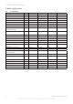
2 Boiler specifications 2 Boiler specifications 2.1 Technical data Description Unit ecoTEC plus 415 ecoTEC plus 418 ecoTEC plus 428 ecoTEC plus 438 Maximum CH heat input (net) kW 15.3 18.9 28.6 38.4 CH heat output (80/60 °C) kW 5.0 - 15.0 5.0 - 18.6 5.3 - 28.2 6.3 - 38.0 CH heat output (50/30 °C) kW 5.3 - 16.2 5.3 - 20.0 5.7 - 30.6 6.8 - 41.0 A A A A 90.5 90.4 90.6 90.8 NOx Class 5 5 5 5 "lP rating" IPX4D IPX4D IPX4D IPX4D mbar 20 20 20 20 MJ/ 37.8 37.
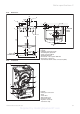
Boiler specifications 2 Dimensions FLUE CL 5 26 160 1 6 48 33 FLUE CL 2 4 FLUE CL OUTSIDE WALL FACE 176 FLUE C 161 L 113 53 340 2.1.2 610 BOILER CL BOILER CL Fig. 2.1 Dimensions in mm 30 133 56 3 15mm GAS CONNECTION 7 375 2.1.3 Installation Legend: 1 Heating return pipe Ø 22 2 Heating flow pipe Ø 22 3 Gas connection Ø 15 4 Hanging bracket 5 Flue hole - flue system 303 933 6 Flue pipe connection 7 Condensate drain outlet connection (Ø 21) 1 5 6 2 7 3 4 Fig. 2.
3 General requirements 3 General requirements 3.1 Preliminary remarks for room sealed appliances This appliance should only be installed with a Vaillant flue system. Install the flue system as detailed in the separate flue installation instructions supplied with this boiler. 3.2 Related documents The installation of the boiler must be in accordance with the relevant requirements of Gas Safety (Installation and Use) Regulations 1998, Health and Safety Document No.
General requirements 3 1435 10 550 3.4 Gas supply The gas supplier should ensure the availability of an adequate supply of gas. A gas meter may only be connected to the service pipe by the supplier of gas or their contractor. An existing meter should be checked to ensure that it is capable of passing the rate of gas supply required. Installation pipes should be fitted in accordance with BS 6891. In IE the current edition of IS 813. Pipe work from the meter to the boiler must be of an adequate size.
3 General requirements 3.5.1 Flue termination The following details refer to both flue systems. a. The terminal must be located where the combustible substances can escape freely at all times. b. A plume of water vapour will sometimes be visible from the flue terminal. Positions where this could be a nuisance should be avoided. c.
General requirements 3 3.8 Domestic hot water cylinder Caution! Single feed indirect cylinders are not suitable. The domestic hot water cylinder must be of the double feed fully indirect coil type. It must be suitable for working at a gauge pressure of 0.35 bar above the safety valve setting. Unvented hot water cylinder 3.8.1 The ecoTEC plus can be connected to an unvented hot water cylinder. Vaillant offer a range of cylinders called uniSTOR with capacities from 125 litres to 310 litres.
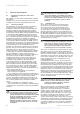
3 General requirements ecoTEC plus 415 pressure loss graph ecoTEC plus 428 pressure loss graph ecoTEC plus 418 pressure loss graph ecoTEC plus 438 pressure loss graph Fig. 3.8 Pressure loss 14 Installation and Servicing ecoTEC plus Supplied by HeatingSpares247.
General requirements 3 3.16 Open vented heating system The boiler must be supplied from an unrestricted water supply taken from a feed and expansion cistern situated at a maximum height of 27 metres (90ft) above the boiler. The cold feed must be 15mm minimum size. The vent must rise continuously and be unrestricted. It is important that the relative positions of the pump, cold feed and open vent are as shown in fig 3.9. Fig. 3.
3 General requirements 3.17 Sealed water systems The installation must comply with the appropriate requirements of the current issue of BS4814, BS5449, BS6759, BS6798 and BS7074 Part 1 and 2. For IE your attention is drawn to the current edition of IS 813. See fig 3.10 for a suggested layout. 3.17.1 Safety valve A safety valve must be fitted to a sealed system.
Boiler installation sequence 4 4 4.1 Boiler installation sequence Boiler location Note! This boiler is not suitable for outdoor installation. This boiler may be installed in any room, although particular attention is drawn to the installation of a boiler in a room containing a bath or shower where reference must be made to the relevant requirements. This boiler is suitable for installation in bathroom zones 2 and 3. 4.1.
4 Boiler installation sequence 4.1.4 Contents included with delivery The Vaillant ecoTEC plus is delivered pre-mounted in a package unit. Check that all the parts have been delivered intact (see fig. 4.2 and table 4.1. DO NOT remove the boiler from the polystyrene base at this stage. Place aside the flue adaptor and connections pack until required. 2 1 3 Note Care should be taken not to scratch the white surface of the boiler casing. 4 .
Boiler installation sequence 4 4.3 Fitting the boiler hanging bracket Reposition the wall template over the flue hole ensuring the template is vertical and mark the position of the fixing holes for the hanging bracket, see fig 4.3. Mark and drill the fixing holes and secure the hanging bracket. Fix the hanging bracket to the wall using the screws supplied. Ensure the uppermost set of screw positions are used (it may be necessary to use additional or alternative fixings to ensure adequate support).
4 Boiler installation sequence 4.3.3 Gas connection Danger! The gas connection may only be made by a competent person. The legal directives and the local regulations for gas supply companies must be observed. Caution! Ensure a stress-relief assembly of the gas pipes to avoid leakages! Caution! The gas regulating block may be tested for leakage only with a maximum pressure of 150 mbar! Higher testing pressures can damage the gas fitting.
Boiler installation sequence 4 4.4 COUPLING Fig. 4.5 Gas and condense connections 22mm compression is the recommended fixing for servicing. Electrical connections Danger! This appliance must be earthed. Electrocution caused by touching live parts can be fatal. Before working on the appliance, turn off the power supply and secure against restart. The boiler must be earthed. All system components shall be of an approved type and all wiring to current I.E.E. wiring regulations.
4 Boiler installation sequence 4.4.1 Connection to the main supply • Lower the electronics box, see fig. 4.7. Opening the electronics box • Unclip the bottom of the electronics box cover and hinge back to reveal the connection plugs. • Feed the power supply flex into the appliance and the electronics box through the cable clamps provided. 4.4.2 Wiring system • Connect the flex to the L, N and earth terminal block, see fig 4.8.
Boiler installation sequence 4 4.4.3 Electrical board layout eBUS accessory connection Burner cable harness X20 X31 X40 Accessory module connection Diagnosis via eBUS vrnet DIALOG X2 X41 ext. flow or return probe outer probe ext.
4 Boiler installation sequence NTC return NTC flow Ignition electrode X 20/8 blue black link X 20/7 black X 20/5 red Fan unit X 20/16 blue (earth) X 20/4 grey(PWM) X 20/3 black (Hall signal) X 20/17 red (24 Vdc) Gas valve assembly X 20/18 red (24 Vdc) X 20/9 blue (earth) green/yellow Chassis earth red X20 black Electronic control box red X2 - + 7 8 9 BUS 24V Pump connection LN 3 4 5 230V fuse T2E 250 Volts green/yellow green/yellow Fig. 4.
Boiler installation sequence 4 4.4.4 Controls Table 4.2 Vaillant controls (used in conjunction with the VR 65 accessory) Controls Item no. Connection VRC 400 (1-circuit controller, weather-controlled) 00 2001 0843 Installation in electronics box or wall-mounted (plug-and play) VRT 360 (room temperature controlled) 00 2001 0842 Wall-mounted, 2-wire bus (plug-and-play) timeSWITCH 140 (timer) 306 760 Installation in electronics box (plug-and-play) Accessory Item no.
5 Commissioning (Part I) 5 Commissioning (Part I) RETAINING DOWEL (2 OFF) Please ensure the “Benchmark” commissioning check list is completed and left with the user. 5.1 Preliminaries - all systems A competent person should carry out commissioning, in accordance with the current issue of BS 6798. Remove the two screws on the inner case then lift the case upwards off the two top retaining dowels. Drop down the electronics box into the service position. Remove the four screws from the chassis panel.
5 Commissioning (Part I) OFFSET ADJUSTMENT THROTTLE ELECTRICAL PLUG PRESSURE TEST POINT GAS CONTROL VALVE Fig. 5.3 Gas control valve 5.1.2 Initial Lighting The lighting procedure of the boiler is fully automated. To prepare the boiler for initial lighting first ensure that all external controls are not calling for heat. For access open the front flap by pulling at the centre of the case strip. Turn on the appliance at control (1), see fig 5.4.
6 Natural gas to LPG conversion 6 Natural gas to LPG conversion The ecoTEC plus is able to be field adjusted for use on LPG – propane G31 gas. To enable conversion the use of a combustion analyser is necessary. Caution! After converting from natural gas to LPG, commission and check boiler function as described in commissioning section of the servicing and installation instructions. NAT.
7 Functional checks commissioning (part II) Commissioning and Service log. 7 Functional checks commissioning (part II) Functional checks Procedure: After installing and checking the gas supply pressure, perform a function check before commissioning the appliance and handing over to the user. • Commission the appliance according to the relevant operating manual. • Check the gas supply pipe, flue system, heating system and the hot water pipes for leaks.
7 Functional checks commissioning (part II) 7.1.3 Final flush of the heating system (hot) • Operate the appliance until the heating system is up to temperature. • Check the heating system for leaks. • Connect a hose to the drain valve located at the lowest position of the heating system. • Shut off the appliance, open the drain valve and all bleed valves on the radiators and allow the water to flow out of the heating system and the boiler quickly and fully. • Close the drain valve.
Inspection and maintenance 8 8 Inspection and maintenance 8.1 Initial inspection To ensure the continued safe and efficient operation of the boiler it is recommended that it is checked and serviced as necessary at regular intervals. The frequency of servicing will depend upon the particular installation conditions and usage, but in general once per year should be adequate. Danger! It is law that all servicing work is carried out by a competent person (CORGI registered).
8 Inspection and maintenance Overview of the inspection and maintenance tasks No. Activity Column 1 Inspection must be carried out once a year 1 Check the air/ gas flue system and ensure it is not blocked, damaged and is fitted correctly. x 2 Measure the gas rate during operation (see table 5.1. inside section 5 commissioning part I). If the gas rate is lower than the minimum gas rate, follow the maintenance schedule in column 2.
Inspection and maintenance 8 8.1.4 General All routine servicing requirements can be achieved by the removal of the front casing, inner case and chassis panel only. Remove the two screws on the underside of the front casing and lift off. Remove the two screws on the front of inner case and lift off, see fig 8.1. Drop down the electronics box into the service position. Remove the four screws from the chassis panel, see fig 8.2. Remove the chassis panel by pulling it out at the top from its retaining slots.
8 Inspection and maintenance 8.1.5 Spark electrode Disconnect the ignition lead and earth lead from the igniter unit and two securing screws at the spark electrode. Withdraw the spark electrode carefully from the combustion chamber, see fig 8.4. Inspect the tips for damage. Clean away any debris and check the spark gap is 3.5 -4.5 mm. Check the electrode gasket for signs of damage and replace if necessary. 8.1.
8 Inspection and maintenance Note! If the burner has to be removed it will require a new gasket when refitted. SECTION THROUGH BURNER DOOR SHOWING POSITION OF SEAL Note! When replacing ensure that the sealing grommet, situated below the gas valve is correctly re-seated. BURNER DOOR SEAL 8.1.7 Combustion chamber and heat exchanger Refer to fig 8.8. Remove loose debris from combustion chamber using a soft brush and vacuum cleaner.
8 Inspection and maintenance 8.1.8 Condensate drain The condense drain does not normally need removing during servicing. To flush the condense drain carefully pour water into the heat exchanger and check that water flows freely to drain. If the condense drain is blocked, refer to parts replacement section 11 for removal. 8.1.9 Inner casing panel seal check Refer to fig 8.9. Check the condition of the seal, replace as required. To replace remove the old seal, thoroughly clean the casing surfaces.
Combustion analysis 9 9 Combustion analysis Note! The boiler is fitted with a combustion analysis test point. A suitable combustion analyser can be connected to this point to establish the combustion performance of the boiler. 9.1 Check CO2 content Refer to table 9.1 and if necessary set (air-ratio adjustment). Note! Combustion analysis must be carried out at annual service if a flue gas analyser is available, if no analyser is available then visual checks should be carried out as per service schedule.
10 Troubleshooting 10 Troubleshooting 10.1 Logical fault finding procedure These checks must be carried out before attempting to use the fault finding guide. 1. Carry out electrical safety checks (see section 4 ‘Wiring system’). 2. Check that the external electricity supply to the boiler is on, and a supply of 230 V~ is present between boiler terminals ‘L’ and ‘N’. 3.
Troubleshooting 10 Display Meaning Charge hot water cylinder (when accessories are fitted): S.20 Warmstart demand S.21 Fan running S.22 Pump running S.23 Ignition sequence S.24 Burner ignited S.25 Fan and water pump running S.26 Fan over run S.27 Pump over run S.28 Anti cycling mode All boilers: S.30 No heating demand from external controls (clamp 3-4 open) S.31 Central heating thermostat knob turned off or no heat demand by the eBUS control unit S.
10 Troubleshooting Display Meaning Display value/adjustable value d. 0 Heating part load Adjustable heating part load in kW (factory setting: max. output) d. 1 Water pump over run time for heating mode 2 - 60 min (factory setting: 5 min) d. 2 Max. burner anti cycling period at 20 °C Flow temperature 2 - 60 min (factory setting: 20 min) d. 3 Hot water flow temperature reading (when accessories are fitted) in °C d.
Troubleshooting 10 Display Meaning Display value/adjustable value d.17 Heating flow/return regulation change over 0 = flow, 1 = return (factory setting: 0) d.18 Pump mode (return) 0 = return, 1 = nonstop, 2 = winter (factory setting: 0) d.
10 Troubleshooting Display Meaning Display value/adjustable value d.78 Storage charging temperature limit (target flow temperature in storage mode, system boilers only) Adjustment range in °C 55 to 90 (Factory setting: 80) d.80 Heating operating hours in h1) d.81 Water heating operating hours (when accessories are fitted) in h1) d.82 Cycles in heating mode Quantity/1001) (3 corresponds 300) d.83 Cycles in hot water operation Quantity/1001) (3 corresponds 300) d.
Troubleshooting 10 Code Meaning Cause F.27 Incorrect sensing of flame Flame detector defective F.
10 Troubleshooting 11 Parts Replacement 10.2 Test programs Special functions can be triggered on the appliances by activating various test programs. These programs are given in detail in the Table 10.5. • The test programs P.0 to P.6 will be started when “Power ON” is turned on and the “+” key is pressed for 5 s. The display shows “P.0”. • Press the “+” key to start counting the test number upwards. • Press the “i” to operate the appliance now and to start the test program.
Parts replacement 11 Note! The ecoTEC plus 428 and 438 fan is secured through an extension piece with two securing screws, check and replace any seals or gaskets if necessary. 11.5 Replacing the heat exchanger For access refer to section 8.1.4. Remove the gas valve, fan and burner refer to the relevant parts of section 8.1.6. Drain the boiler. Remove the clip securing the clear condense pipe to heat exchanger.
11 Replacement parts 12 Recycling and disposal 13 Vaillant service 11.7 Replacing electronics and display Danger! Before replacing the component, comply with the safety instructions in Section 11.1. • Comply with the assembly and installation manuals provided with the spare parts. Replacing display or electronics If you are replacing only one of the two components, the parameter adjustment functions automatically.
Appendix 14 Installation and Servicing ecoTEC plus Supplied by HeatingSpares247.
Installation and Servicing ecoTEC plus Supplied by HeatingSpares247.
Installation and Servicing ecoTEC plus Supplied by HeatingSpares247.
Notes 50 Installation and Servicing ecoTEC plus Supplied by HeatingSpares247.
Notes Installation and Servicing ecoTEC plus Supplied by HeatingSpares247.
Supplied by HeatingSpares247.
834449_09GB_082006.qxd 10.08.
834449_09GB_082006.qxd 10.08.2006 12:20 Seite 2 Supplied by HeatingSpares247.
834449_09GB_082006.qxd 10.08.2006 12:20 Seite 3 Pages 4 - 36 Standard Concentric Systems Ø 60/100 (Galvanized steel air duct/plastic flue duct) PART 2 Pages 37 - 59 Optional Concentric System Ø 80/125 (Galvanized steel air duct/plastic flue duct) Supplied by HeatingSpares247.
834449_09GB_082006.qxd 10.08.2006 12:20 Seite 4 CONTENTS: PART 1 CONCENTRIC 60/100 The air/flue duct must be installed by a suitably qualified service provider, which is responsible for observing the relevant specifications, regulations and standards.
10.08.2006 12:20 Seite 5 REQUIREMENTS Regulations and standards to be observed ☞ Vaillant ecoMAX/ecoTEC boilers are certified as heating boilers with corresponding flue systems according to EC Directive 90/396/EEC on gas-fired devices. This installation manual is covered by this certification and is referred to in the design approval test certificate. ☞ These instructions should be read in conjunction with the instructions for installation and servicing supplied with the boiler.
834449_09GB_082006.qxd 10.08.2006 12:20 Seite 6 PLANNING THE AIR/FLUE DUCT LAYOUT Alternative termination accessories available 303 900 = Vertical air/flue duct (black) 303 933 = Horizontal air/flue duct 303 936 = Horizontal telescopic air/flue duct Optional connection accessories 303 900 303 933 303 936 Accy. No.
834449_09GB_082006.qxd 10.08.2006 12:20 Seite 7 PLANNING THE AIR/FLUE DUCT LAYOUT PART 1 CONCENTRIC 60/100 Air/flue duct extension 470 mm Ø 60/100 Vaillant Accy. No.: 303 902 Air/flue duct extension 970 mm, Ø 60/100 Vaillant Accy. No.: 303 903 GU_LAZ 70/0 Air/flue duct extension 1970 mm, Ø 60/100 Vaillant Accy. No.: 303 905 Fig. 1.1: Extensions, Ø 60/100 Elbow, 87°, Ø 60/100 Vaillant Accy. No.: 303 910 27 27 18 27 18 18 Bends, 45° (pack of 2), Ø 60/100 Vaillant Accy. No.: 303 911 Fig. 1.
834449_09GB_082006.qxd 10.08.2006 12:20 Seite 8 PLANNING THE AIR/FLUE DUCT LAYOUT 250 Adjustable flue support clips, Ø 100 (pack of 3) Vaillant Accy. No.: 303 935 Fig. 1.5: Flue support clips, Ø 100 Telescopic extension (PP), Ø 60/100 440 mm - 690 mm Vaillant Accy. No.: 303 906 440 – 690 Fig. 1.6: Telescopic extension, Ø 60/100 33 – 56 Offset section, Ø 60/100 Vaillant Accy. No.: 303 919 Fig. 1.7: Offset section, Ø 60/100 303919_IAx 290 – 374 155 Sliding sleeve (PP), Ø 60/100 Vaillant Accy.
10.08.2006 12:20 Seite 9 PLANNING THE AIR/FLUE DUCT LAYOUT 25 PART 1 CONCENTRIC 60/100 Adjustable roof tile for pitched roof Vaillant Accy. No.: 009 076 (black) 132 5 8 GU_LAZ 41/0 49 Fig. 1.9: Adjustable roof tile for pitched roof Flexible pitched roof seal (black) Vaillant Accy. No.: 303 980 495 132 495 Fig. 1.10: Flexible pitched roof seal Flat roof penetration collar Vaillant Accy. No.: 009 056 130 153 834449_09GB_082006.qxd 390 Fig. 1.
834449_09GB_082006.qxd 10.08.2006 12:20 Seite 10 PLANNING THE AIR/FLUE DUCT LAYOUT Variable termination kit - black Vaillant Accy. No.: 303 942 For 303 933 and 303 936 only Variable termination kit - white Vaillant Accy. No.: 303 946 For 303 933 and 303 936 only Fig. 1.13: Variable termination kit Extension pipe for variable termination kit Ø 60 mm 1 m - black including 1 support clip Vaillant Accy. No.
834449_09GB_082006.qxd 10.08.2006 12:20 Seite 11 PLANNING THE AIR/FLUE DUCT LAYOUT 60 PART 1 CONCENTRIC 60/100 Flue support clip, Ø 60 mm delivered with kits Fig. 1.17: Flue support clip, Ø 60 mm Maximum flue lengths for use with ecoMAX ecoMAX Accessories 613/2 E 618/2 E 622/2 E 824/2 E 828/2 E 635/ E 835/ E pro 18 E pro 28 E 8.0 m incl. 1 elbow 87° 7.0 m incl. 1 elbow 87° 8.0 m incl. 1 elbow 87° 4.0 m incl. 1 elbow 87° 10.0 m incl. 1 elbow 87° Accy. No. Horizontal 303 933 Max.
834449_09GB_082006.qxd 10.08.2006 12:20 Seite 12 PLANNING THE AIR/FLUE DUCT LAYOUT Maximum flue lengths for use with ecoTEC ecoTEC plus 612 plus 615 plus 618 Accessories Accy. No. Horizontal flue systems 303 933 Max. permitted concentric flue length Fig. 1.18 plus 624 plus 824 plus 630 plus 831 plus 637 plus 837 pro 24 pro 28 plus plus plus plus 415 418 428 438 10.0 m 8.0 m 8.0 m 8.0 m 8.0 m 5.5 m incl. incl. incl. incl. incl. incl.
834449_09GB_082006.qxd 10.08.2006 12:20 Seite 13 Maximum flue length Fig. 1.19: Vertical flue systems Flue length outside Fig. 1.18: Horizontal flue systems LAS Euro B/S 074/0 LAS Euro B/S 074/0 Maximum flue length PART 1 CONCENTRIC 60/100 PLANNING THE AIR/FLUE DUCT LAYOUT Concentric flue length Fig. 1.20: Horizontal flue system installed with vertical termination kit Supplied by HeatingSpares247.
834449_09GB_082006.qxd 10.08.2006 12:20 Seite 14 INSTALLING THE AIR/FLUE DUCT SLIDING SLEEVE 3 5 Fig. 2.0: Installing the sliding sleeve 14 ☞ NOTE: For installations where there is insufficient movement to allow fitting of the flue into flue outlet, a sliding sleeve (Accy. No. 303 915) is available. When using the sliding sleeve both the air and flue ducts of the last extension must be shortened by a further 95 mm.
834449_09GB_082006.qxd 10.08.2006 12:20 Seite 15 INSTALLATION OF THE HORIZONTAL AIR/FLUE DUCT Horizontal air/flue duct 754 Accy No.: 303 933 (Length 0.75 m) 65 Contents of the accessory: • Horizontal air/flue duct • 87° elbow • 1 x 48 mm air duct clamp • 1 x 30 mm air duct clamp • Internal trim ring Ø 100 • External wall seal.
834449_09GB_082006.qxd 10.08.2006 12:20 Seite 16 INSTALLATION OF THE HORIZONTAL AIR/FLUE DUCT (TOP OUTLET) • Once the position of the flue exit hole has been determined, the hole should be cut through the wall using a core drill of 125 mm diameter. Note: If access can be gained to the proposed flue exit point from outside the dwelling, the hole can be cut with a 107 mm core drill and the flue external wall seal fitted from outside the dwelling.
834449_09GB_082006.qxd 10.08.2006 12:20 Seite 17 • Push the air/flue duct assembly (1) including the flexible external seal through the wall until the seal clears the outside face of the wall and pull air/flue duct back towards the boiler until the external seal touches the outside wall (fig. 3.8 and fig 3.12). 87 13 Fig. 3.12 LAS Euro B/S 001/0GB 1 • Ensure that the air/flue duct (1) is centred in the hole and the terminal is correctly positioned with the inlet grille at the bottom (fig 3.
834449_09GB_082006.qxd 10.08.2006 12:20 Seite 18 INSTALLATION OF THE TELESCOPIC HORIZONTAL AIR/FLUE DUCT IMPORTANT: The air/flue duct is not concentric and the air duct has a slope of 1.5° (if the air flue duct is not cut). The hole through the wall can therefore be drilled horizontally with no slope. Horizontal telescopic air/flue duct 405 - 610 Accy No.: 303 936 (Length 0.4 - 0.61 m) 48 65 Fig. 3.
834449_09GB_082006.qxd 10.08.2006 12:20 Seite 19 • Once the position of the flue exit hole has been determined, the hole should be cut through the wall using a core drill of 125 mm diameter. Note: If access can be gained to the proposed flue exit point from outside the dwelling, the hole can be cut with a 107 mm core drill and the flue external wall seal fitted from outside the dwelling. Fig. 3.
834449_09GB_082006.qxd 10.08.2006 12:20 Seite 20 INSTALLATION OF THE TELESCOPIC HORIZONTAL AIR/FLUE DUCT (TOP OUTLET) • Push the air/flue duct assembly (1) including the flexible external seal through the wall until the seal clears the outside face of the wall and pull air/flue duct back towards the boiler until the external seal touches the outside wall (fig. 3.14 and fig. 3.18). 87 13 Fig. 3.
10.08.2006 12:20 Seite 21 INSTALLATION OF THE BLACK TERMINAL KIT Black terminal kit Accy. No.: 303 934 Contents of the accessory: • Black terminal • External wall seal Fig. 3.19: Black kit Assembly Before installing the flue duct Fig. 3.20: Releasing the catches • Use an 8 mm screwdriver to bend the catches inwards (fig. 3.20). • Pull the terminal together with the flue duct out of the air duct (fig. 3.21).
834449_09GB_082006.qxd 10.08.2006 12:20 Seite 22 INSTALLATION OF THE BLACK TERMINAL KIT Assembly After installing the flue duct Danger! Before starting work, shut down the appliance and prevent it from being switched on unintentionally. Fig. 3.23: Flue duct • Remove the wall seal from the terminal. • Use an 8 mm screwdriver to bend the catches inwards (fig. 3.20). • Pull the terminal together with the flue duct out of the air duct (fig. 3.21).
834449_09GB_082006.qxd 10.08.2006 12:20 Seite 23 INSTALLATION OF THE VARIABLE TERMINATION KIT Important: The flue outlet of the variable termination must face directly upwards. PART 1 CONCENTRIC 60/100 Flue Terminal Clearances Minimum flue terminal clearances are defined in BS5440, and these must apply unless the boiler manufacturer has received approval to quote smaller clearances that are not safety critical.
834449_09GB_082006.qxd 10.08.2006 12:20 Seite 24 INSTALLATION OF THE VARIABLE TERMINATION KIT • Unlock the catch between the terminal and the flue duct by twisting them against each other (fig. 4.5). • Pull the terminal out of the flue duct. • Push the variable terminal onto the flue duct. ☞ Please note: The catch on the top of the variable terminal must lock firmly into the notch in the flue duct (fig. 4.6). Fig. 4.5: Unlocking the catch Caution! Make sure the seal fits tightly.
834449_09GB_082006.qxd 10.08.2006 12:20 Seite 25 • Fit the pipes and bends, working from the variable terminal to the selected location for the flue exit using support clips supplied fig 4.8, 4.9, 4.10 or 4.11. Caution! Pipe extensions must be fixed to the wall using pipe clamps. Use one clamp for each extension directly beside the sleeve. Fit another clamp to the extension after each 87° bend (fig. 4.9). Caution! The extension pipe expands when heated. Leave 1 cm expansion space in each sleeve.
834449_09GB_082006.qxd 10.08.2006 12:20 Seite 26 INSTALLATION OF THE VARIABLE TERMINATION KIT Fig. 4.10: Installation of basic kit with two additional 87° bends showing position of support clips Fig. 4.11: Installation of basic kit with two additional 45° bends showing position of support clips 26 Supplied by HeatingSpares247.
834449_09GB_082006.qxd 10.08.2006 12:20 Seite 27 min 400 mm min 100 mm Routing around roof eaves When routing the variable termination kit around the roof eaves, additional lengths of M8 threaded bar will be required for the support brackets. Threaded bar can be purchased from most local merchants. • Change the bird protection grille from the 87° elbow to the extension installed at the end. ☞ If using the 87° elbow, use the seal from the pipe extension.
834449_09GB_082006.qxd 10.08.2006 12:20 Seite 28 INSTALLATION OF THE VERTICAL AIR/FLUE DUCT ☞ Observe the maximum flue lengths as detailed in table on page 11. Vertical air/flue duct Accy. No.: 303 900 (black) 40 880 1435 550 Contents of the accessory: • Vertical air/flue duct and terminal assembly • 40 mm air duct clamp • Fixing bracket ☞ See page 6 et seq. for details of air/flue duct elements. Fig. 5.
834449_09GB_082006.qxd 10.08.2006 12:20 Seite 29 INSTALLATION OF THE VERTICAL AIR/FLUE DUCT 550 5 20 885 –5 0 1 0-5 6 Ø100 8 2 750 4 100- 110 * 3 8 * = 190 mm ecoMAX combination and system boilers * = 176 mm ecoMAX pro and ecoTEC plus open vent * = 125 mm ecoTEC plus system & combination Fig. 5.
834449_09GB_082006.qxd 10.08.2006 12:20 Seite 30 INSTALLATION OF THE VERTICAL AIR/FLUE DUCT Flat-roof installation 550 5 cold roof warm roof 885 1 120 7 4 7 Fig. 5.
4449_09GB_082006.qxd 10.08.2006 12:20 Seite 31 FITTING AIR/FLUE DUCT EXTENSIONS Use a saw, tin-snips, etc. to cut tubes to size. ☞ No tools are required when separating extensions for cutting to size air and flue tubes separately. When doing so, the flue conduit should be twisted into a position where the shoulders on the plastic tube can be pushed through the spacer-piece. After cutting to size, refit the flue conduit and secure it to the air conduit.
834449_09GB_082006.qxd 10.08.2006 12:20 Seite 32 FITTING AIR/FLUE DUCT EXTENSIONS How to install 2x 87° elbows 2 1 Fig. 6.1: Arrangement of 2 x 87° elbows – View from above • When using 2 x 87° elbows follow fig. 6.1 to fig. 6.3 to avoid obstructions on outer wall. Note: The elbows must be correctly aligned to avoid undue stress on the joints and risk of leakage.
834449_09GB_082006.qxd 10.08.2006 12:20 Seite 33 FITTING AIR/FLUE DUCT EXTENSIONS 90 ☞ Note: The elbows must be correctly aligned to avoid undue stress on the joints an risk of leakage. The elbow fitted to the top of the boiler (1) should be twisted by 3° to ensure that the second 87° elbow (2) exits the wall perpendicular. When using 87° elbow install with a slope of 3° between wall and air-flue pipe (fig. 6.4) or use 2 x 45° elbows (fig. 6.5). * 2 1 max. 5 m *=3 max. 5 m Fig. 6.
834449_09GB_082006.qxd 10.08.2006 12:20 Seite 34 FITTING AIR/FLUE DUCT EXTENSIONS How to install 87° elbows Accy. No.: 303 910 ☞ Note: The elbow delilvered with the flue kits 303 933 and 303 936 is not the same dimension as shown here. 1 90 Offset Example: Length of air conduit 95 An offset of 400 mm is measured. This value is then used, along with the table below, to determine the length of the air conduit ( = 190 mm in this case).
10.08.2006 12:20 Seite 35 FITTING AIR/FLUE DUCT EXTENSIONS How to install 45° elbows 10 Le ng th of a ir co nd ui t An offset of 400 mm is measured. This value is then used, along with the table below, to determine the length of the air conduit (= 284 mm) and the height (= 420 mm). Important: This gives a corresponding exhaust-conduit length of 284 + 40 = 324 mm. Fig. 6.4: Installation of 45° bends Table 6.
834449_09GB_082006.qxd 36 10.08.2006 12:20 Seite 36 Supplied by HeatingSpares247.
834449_09GB_082006.qxd 10.08.
834449_09GB_082006.qxd ¤ 10.08.2006 12:20 Seite 38 REQUIREMENTS Regulations and standards to be observed ☞ Vaillant ecoMAX/ecoTEC boilers are certified as heating boilers with corresponding flue systems according to EC Directive 90/396/EEC on gas-fired devices. This installation manual is covered by this certification and is referred to in the design approval test certificate.
834449_09GB_082006.qxd 10.08.2006 12:20 Seite 39 PLANNING THE AIR/FLUE DUCT LAYOUT Alternative termination accessories available 303 200 = Vertical air/flue duct (black) 303 209 = Horizontal air/flue duct 303 926 = Appliance connection piece 303 200 303 209 Accy. No.
834449_09GB_082006.qxd 10.08.2006 12:20 Seite 40 PLANNING THE AIR/FLUE DUCT LAYOUT 18 58 25 Appliance connection piece Ø 80/125 Vaillant Accy. No.: 303 926 (with 2 measuring apertures) Fig. 1.1: Appliance connection piece Air/flue duct extension (PPs) 470 mm, Ø 80/125 Vaillant Accy. No.: 303 202 Air/flue duct extension (PPs) 970 mm, Ø 80/125 Vaillant Accy. No.: 303 203 GU_LAZ 70/0 Air/flue duct extension (PPs) 1970 mm, Ø 80/125 Vaillant Accy. No.: 303 205 Fig. 1.
10.08.2006 12:20 Seite 41 PLANNING THE AIR/FLUE DUCT LAYOUT Sliding sleeve (PPs), Ø 80/125 Vaillant Accy. No.: 303 215 164 GU_LAZ 76/0 120 Fig. 1.5: Sliding sleeve, Ø 80/125 Adjustable roof tiles for pitched roof Vaillant Accy. No.: 009 076 (black) 132 5 PART 2 CONCENTRIC 80/125 25 8 GU_LAZ 41/0 49 Fig. 1.6: Adjustable roof tile for pitched roof Flexible pitched roof seal (black) Vaillant Accy. No.: 303 980 495 132 495 Fig. 1.
834449_09GB_082006.qxd 10.08.2006 12:20 Seite 42 PLANNING THE AIR/FLUE DUCT LAYOUT Maximum flue lengths for use with ecoMAX ecoMAX Accessories Accy. No. Horizontal flue systems 303 209 Max. permitted concentric flue length 613/2 E 618/2 E 622/2 E pro 18 E pro 28 E 13.0 m incl. 1 elbow 87° 25.0 m incl. 1 elbow 87° 30.0 m incl. 1 elbow 87° 20.0 m incl. 1 elbow 87° Maximum length of flue is reduced by 2.5 m for each additional 90° elbow. Maximum length of flue is reduced by 1.
834449_09GB_082006.qxd 10.08.2006 12:20 Seite 43 PLANNING THE AIR/FLUE DUCT LAYOUT Maximum flue lengths for use with ecoTEC ecoTEC Accessories Accy. No. 303 209 Max. permitted Horizontal concentric flue systems flue length plus plus plus plus plus plus 612 plus 615 13.0 m incl. 1 elbow 87° 618 624 630 824 831 25.0 m incl. 1 elbow 87° Maximum length of flue is reduced by 2.5 m for each additional 90° elbow. 303 200 Max. permitted Vertical concentric flue systems flue length 14.0 m 27.
834449_09GB_082006.qxd 10.08.2006 12:20 Seite 44 PLANNING THE AIR/FLUE DUCT LAYOUT LAS Euro B/S 074/0 Maximum flue length Fig. 1.10 44 LAS Euro B/S 074/0 Maximum flue length Fig. 1.9 Supplied by HeatingSpares247.
834449_09GB_082006.qxd 10.08.2006 12:20 Seite 45 CHANGING THE APPLIANCE CONNECTION-PIECE Installation Accy No.: 303 926 2 1 The appliance is supplied ready-fitted with the connection-piece for the 60/100 air/flue duct system. • Loosen the four screws (2) and pull the appliance connectionpiece (1) upwards to remove it. • Refit the fixing screws (2). Fig. 2.0: Fitting the appliance connection-piece The seals are sensitive to mineral oil-based grease products.
834449_09GB_082006.qxd 10.08.2006 12:20 Seite 46 INSTALLATION OF THE SLIDING SLEEVE 3 5 Fig. 3.0: Installing the sliding sleeve 46 ☞ NOTE: For installations where there is insufficient movement to allow fitting of the flue into flue outlet, a sliding sleeve (Accy. No. 303 215) is available. When using the sliding sleeve both the air and flue ducts of the last extension must be shortened by a further 85 mm.
834449_09GB_082006.qxd 10.08.2006 12:20 Seite 47 ☞ Observe the maximum flue lengths as detailed in table on page 42. 1103 70 70 15 IMPORTANT: The air/flue duct is not concentric and the air duct has a slope of 1.5° (if the air flue duct is not cut). The hole through the wall can therefore be drilled horizontally with no slope. Horizontal air/flue duct Vaillant Accy No.
834449_09GB_082006.qxd 10.08.2006 12:20 Seite 48 INSTALLATION OF THE HORIZONTAL AIR/FLUE DUCT Ø 80/125 WITH EXTENSIONS IMPORTANT: The air/flue duct is not concentric and the air duct has a slope of 1.5° (if the air flue duct is not cut). The hole through the wall can therefore be drilled horizontally with no slope. Where extensions are used, these must be installed with a slope at 3° ± 1° (equivalent to 50 mm ± 20 mm rise per metre length) to ensure that condensate dows not remain in the sleeve.
834449_09GB_082006.qxd 10.08.2006 12:20 Seite 49 A Fig. 4.5 Mark air duct here 10 mm LAS Euro B/S 084/0 Dimension A + 20 Dimension 60 mm mm Fig. 4.6 15 mm 25 mm Fig. 4.7 LAS Euro B/S 080/0 Mark flue duct here • Taking each extension to be used, fit the flue duct into the air duct and secure using the 3 screws provided. • For ease of measuring and marking the air/flue duct extensions, assemble them loosely together with the air/flue duct and terminal assembly as shown (fig. 4.6).
834449_09GB_082006.qxd 10.08.2006 12:20 Seite 50 INSTALLATION OF THE HORIZONTAL AIR/FLUE DUCT Ø 80/125 WITH EXTENSIONS 220 3 15 Fig. 4.8: Installing the horizontal wall duct 50 LGU_LAZ 384/0_IT 1 • Push the assembled air/flue duct and terminal assembly through the flue exit hole until it protrudes 220 mm out from the outside wall. • Ensure that the terminal is correctly positioned with the air inlet grille at the bottom.
834449_09GB_082006.qxd 10.08.2006 12:20 Seite 51 INSTALLATION OF THE HORIZONTAL AIR/FLUE DUCT (80/125 Ø) Indirect installation • Fit the wall mounting (2). 6 • Install the appliance (3) with reference to the installation and servicing instructions supplied with the boiler. 253 4 ** 82 - 90 • Join the 87° elbow to the appliance connection piece.
834449_09GB_082006.qxd 10.08.2006 12:20 Seite 52 INSTALLATION OF THE VERTICAL AIR/FLUE DUCT Vertical air/flue duct Accy. No.: 303 200 (black) Contents of the accessory: • Vertical air/flue duct and terminal assembly • Adapter (air) for Ø 110/125 • 70 mm air duct clamp • Fixing bracket Fig. 5.1: Vertical roof duct GU_LAZ 81/0 880 70 1530 650 ☞ Observe the maximum flue lengths as detailed in table on page 42. ☞ See page 41 et seq. for details of air/flue duct elements.
834449_09GB_082006.qxd 10.08.2006 12:20 Seite 53 INSTALLATION OF THE VERTICAL AIR/FLUE DUCT 790 5 740 20 –5 0 1 0-5 6 Ø125 8 2 82 - 90 4 750 * 3 8 750 mm ecoMAX combination and system boilers 530 mm ecoMAX pro and ecoTEC plus open vent (top holes of bracket) 622 mm ecoTEC plus system & combination 7 * = 190 mm ecoMAX combination and system boilers * = 176 mm ecoMAX pro and ecoTEC plus open vent * = 125 mm ecoTEC plus system & combination Fig. 5.
834449_09GB_082006.qxd 10.08.2006 12:20 Seite 54 INSTALLATION OF THE VERTICAL AIR/FLUE DUCT Flat-roof installation 650 5 cold roof warm roof 880 1 120 6 2 7 4 7 Fig. 5.
834449_09GB_082006.qxd 10.08.2006 12:20 Seite 55 FITTING AIR/FLUE DUCT EXTENSIONS How to add extensions Use a saw, tin-snips, etc. to cut tubes to size. L air 1. 2 25 2. 1 15 + 40 mm Fig. 6.1: Cutting tubes to size ☞ The seals are sensitive to mineral oil-based grease products. For this reason, the seals must not be greased. If the seals need wetting to aid in installation, use water only.
834449_09GB_082006.qxd 10.08.2006 12:20 Seite 56 FITTING AIR/FLUE DUCT EXTENSIONS How to install 2x 87° elbows 2 1 • When using 2 x 87° elbows follow fig. 6.1 to fig. 6.3 to avoid obstructions on outer wall. Note: The elbows must be correctly aligned to avoid undue stress on the joints and risk of leakage. The elbow fitted to the top of the boiler (1) should be twisted by 3° to ensure that the second 87° elbow (2) exits the wall perpendicular. Fig. 6.
834449_09GB_082006.qxd 10.08.2006 12:20 Seite 57 FITTING AIR/FLUE DUCT EXTENSIONS max. 5 m • When using elbows for long flue runs in a corner follow fig. 6.4 and fig. 6.5 to avoid obtrsuctions. 90 ☞ Note: The elbows must be correctly aligned to avoid undue stress on the joints an risk of leakage. The elbow fitted to the top of the boiler (1) should be twisted by 3° to ensure that the second 87° elbow (2) exits the wall perpendicular.
834449_09GB_082006.qxd 10.08.2006 12:20 Seite 58 FITTING AIR/FLUE DUCT EXTENSIONS How to install 87° elbows Accy. No.: 303 210 Example: Length of air conduit 95 Important: This gives a corresponding exhaust-conduit length of 190 + 40 = 230 mm. 10 95 10 GU_LAZ 102/2GB An offset of 400 mm is measured. This value is then used, along with the table below, to determine the length of the air conduit (= 190 mm in this case). 1 90 Offset Fig. 6.3: Installation of 90° elbows Table 6.
834449_09GB_082006.qxd 10.08.2006 12:20 Seite 59 FITTING AIR/FLUE DUCT EXTENSIONS How to install 45° elbows Height Accy. No.: 303 211 Example: 10 Le ng th of a ir co nd ui t An offset of 400 mm is measured. This value is then used, along with the table below, to determine the length of the air conduit (= 284 mm) and the height (= 420 mm). 10 Offset GU_LAZ 103/2GB Important: This gives a corresponding exhaust-conduit length of 284 + 40 = 324 mm. Fig. 6.
834449_09GB_082006.qxd 60 10.08.2006 12:20 Seite 60 Supplied by HeatingSpares247.
834449_09GB_082006.qxd 10.08.2006 12:20 Seite 61 Supplied by HeatingSpares247.
834449_09GB_082006.qxd 62 10.08.2006 12:20 Seite 62 Supplied by HeatingSpares247.
834449_09GB_082006.qxd 10.08.2006 12:20 Seite 63 Supplied by HeatingSpares247.
10.08.2006 12:20 Seite 64 834449_09 GB 082006 834449_09GB_082006.qxd Supplied by HeatingSpares247.
Spare part catalogue 0020010870.01 GB 03/2006 Wall-hung boilers ecoTEC plus 824, 831, 837, 612, 615, 618, 624, 630, 637 VUW 246/3-5 VUW 246/3-5 R1 VUW 316/3-5 VUW 316/3-5 R1 VUW 376/3-5 R1 VU 126/3-5 VU 126/3-5 R1 VU 156/3-5 VU 156/3-5 R1 VU 186/3-5 VU 186/3-5 R1 VU 246/3-5 VU 246/3-5 R1 VU 306/3-5 VU 306/3-5 R1 VU 376/3-5 R1 Supplied by HeatingSpares247.
Supplied by HeatingSpares247.
Content ecoTEC plus 824 VUW 246/3-5 + R1 ecoTEC plus 831 VUW 316/3-5 + R1 ecoTEC plus 837 VUW 376/3-5 R1 General view of sheet Page 3 04 Burner Page 4 06 Heat exchanger Page 6 07 Casing parts Page 8 08 Connection parts (Hydroblock) Page 10 08a Connection parts Page 14 08b Connection parts (Acc.
2 0020010870.01 GB 03/2006 Supplied by HeatingSpares247.
General view of sheet ecoTEC plus 824 VUW 246/3-5 + R1 ecoTEC plus 831 VUW 316/3-5 + R1 ecoTEC plus 837 VUW 376/3-5 R1 02-00-077 Subject to alteration ! Attention: Please take the gross price from the valid price list ! Supplied by HeatingSpares247.
04 Burner ecoTEC plus 824 VUW 246/3-5 + R1 ecoTEC plus 831 VUW 316/3-5 + R1 ecoTEC plus 837 VUW 376/3-5 R1 4 0020010870.01 GB 03/2006 Supplied by HeatingSpares247.
04 Burner ecoTEC plus 824 VUW 246/3-5 + R1 ecoTEC plus 831 VUW 316/3-5 + R1 ecoTEC plus 837 VUW 376/3-5 R1 Pos. Art.
06 Heat exchanger ecoTEC plus 824 VUW 246/3-5 + R1 ecoTEC plus 831 VUW 316/3-5 + R1 ecoTEC plus 837 VUW 376/3-5 R1 6 0020010870.01 GB 03/2006 Supplied by HeatingSpares247.
06 Heat exchanger ecoTEC plus 824 VUW 246/3-5 + R1 ecoTEC plus 831 VUW 316/3-5 + R1 ecoTEC plus 837 VUW 376/3-5 R1 Pos. Art.
07 Casing parts ecoTEC plus 824 VUW 246/3-5 + R1 ecoTEC plus 831 VUW 316/3-5 + R1 ecoTEC plus 837 VUW 376/3-5 R1 8 0020010870.01 GB 03/2006 Supplied by HeatingSpares247.
07 Casing parts ecoTEC plus 824 VUW 246/3-5 + R1 ecoTEC plus 831 VUW 316/3-5 + R1 ecoTEC plus 837 VUW 376/3-5 R1 Pos. Art.-No 01 180932 Part 02-07-073 flue adapter 60/100 02 147392 cap (set of 5) 03 981232 packingring 04 981233 packingring 05 180935 covering, cpl. VUW 246/3-5, with parts 06, 07, 08, 09, 10, 11 05 180935 covering, cpl. VUW 246/3-5 R1, with parts 06, 07, 08, 09, 10, 11 05 180935 covering, cpl. VUW 316/3-5, with parts 06, 07, 08, 09, 10, 11 05 180935 covering, cpl.
08 Connection parts (Hydroblock) ecoTEC plus 824 VUW 246/3-5 + R1 ecoTEC plus 831 VUW 316/3-5 + R1 ecoTEC plus 837 VUW 376/3-5 R1 10 0020010870.01 GB 03/2006 Supplied by HeatingSpares247.
08 Connection parts (Hydroblock) ecoTEC plus 824 VUW 246/3-5 + R1 ecoTEC plus 831 VUW 316/3-5 + R1 ecoTEC plus 837 VUW 376/3-5 R1 Pos. Art.
08 Connection parts (Hydroblock) ecoTEC plus 824 VUW 246/3-5 + R1 ecoTEC plus 831 VUW 316/3-5 + R1 ecoTEC plus 837 VUW 376/3-5 R1 12 0020010870.01 GB 03/2006 Supplied by HeatingSpares247.
08 Connection parts (Hydroblock) ecoTEC plus 824 VUW 246/3-5 + R1 ecoTEC plus 831 VUW 316/3-5 + R1 ecoTEC plus 837 VUW 376/3-5 R1 Pos. Art.-No Part 02-08-115 Type, note 35 - - 36 981165 packingring (set of 10) not available as spare part, see pos.
08a Connection parts ecoTEC plus 824 VUW 246/3-5 + R1 ecoTEC plus 831 VUW 316/3-5 + R1 ecoTEC plus 837 VUW 376/3-5 R1 14 0020010870.01 GB 03/2006 Supplied by HeatingSpares247.
08a Connection parts ecoTEC plus 824 VUW 246/3-5 + R1 ecoTEC plus 831 VUW 316/3-5 + R1 ecoTEC plus 837 VUW 376/3-5 R1 Pos. Art.-No 01 180946 Part 02-08-120 connection tube, cpl. 02 193537 packingring (set of 10) 03 103415 packingring (set of 10) 04 103417 clip (set of 10) 05 178992 clip (set of 10) 06 180948 connection tube, cpl. 07 193539 packingring (set of 10) 08 180949 connection tube, cpl.
08b Connection parts (Acc.) ecoTEC plus 824 VUW 246/3-5 + R1 ecoTEC plus 831 VUW 316/3-5 + R1 ecoTEC plus 837 VUW 376/3-5 R1 16 0020010870.01 GB 03/2006 Supplied by HeatingSpares247.
08b Connection parts (Acc.) ecoTEC plus 824 VUW 246/3-5 + R1 ecoTEC plus 831 VUW 316/3-5 + R1 ecoTEC plus 837 VUW 376/3-5 R1 Pos. Art.-No 01 082782 Part 02-08-125 gas shut-off valve, cpl. 01 082782 gas shut-off valve, cpl. VUW 246/3-5 R1 01 082782 gas shut-off valve, cpl. VUW 316/3-5 01 082782 gas shut-off valve, cpl. VUW 316/3-5 R1 01 082794 gas shut-off valve, cpl.
12 Control box ecoTEC plus 824 VUW 246/3-5 + R1 ecoTEC plus 831 VUW 316/3-5 + R1 ecoTEC plus 837 VUW 376/3-5 R1 18 0020010870.01 GB 03/2006 Supplied by HeatingSpares247.
12 Control box ecoTEC plus 824 VUW 246/3-5 + R1 ecoTEC plus 831 VUW 316/3-5 + R1 ecoTEC plus 837 VUW 376/3-5 R1 Pos. Art.-No Part 02-12-046 01 193582 casing, cpl. 02 251955 fuse 2.0 AT (set of 10) 03 117319 knobs, cpl. grey (3 knobs) 04 0020028736 printed circuit board 05 117321 display 06 180982 pressure gauge Type, note 2.
20 0020010870.01 GB 03/2006 Supplied by HeatingSpares247.
General view of sheet ecoTEC plus 612 VU 126/3-5 + R1, ecoTEC plus 615 VU 156/3-5 + R1 ecoTEC plus 618 VU 186/3-5 + R1, ecoTEC plus 624 VU 246/3-5 + R1 ecoTEC plus 630 VU 306/3-5 + R1, ecoTEC plus 637 VU 376/3-5 R1 02-00-077 Subject to alteration ! Attention: Please take the gross price from the valid price list ! Supplied by HeatingSpares247.
04 Burner ecoTEC plus 612 VU 126/3-5 + R1, ecoTEC plus 615 VU 156/3-5 + R1 ecoTEC plus 618 VU 186/3-5 + R1, ecoTEC plus 624 VU 246/3-5 + R1 ecoTEC plus 630 VU 306/3-5 + R1, ecoTEC plus 637 VU 376/3-5 R1 22 0020010870.01 GB 03/2006 Supplied by HeatingSpares247.
04 Burner ecoTEC plus 612 VU 126/3-5 + R1, ecoTEC plus 615 VU 156/3-5 + R1 ecoTEC plus 618 VU 186/3-5 + R1, ecoTEC plus 624 VU 246/3-5 + R1 ecoTEC plus 630 VU 306/3-5 + R1, ecoTEC plus 637 VU 376/3-5 R1 Pos. Art.
04 Burner ecoTEC plus 612 VU 126/3-5 + R1, ecoTEC plus 615 VU 156/3-5 + R1 ecoTEC plus 618 VU 186/3-5 + R1, ecoTEC plus 624 VU 246/3-5 + R1 ecoTEC plus 630 VU 306/3-5 + R1, ecoTEC plus 637 VU 376/3-5 R1 24 0020010870.01 GB 03/2006 Supplied by HeatingSpares247.
04 Burner ecoTEC plus 612 VU 126/3-5 + R1, ecoTEC plus 615 VU 156/3-5 + R1 ecoTEC plus 618 VU 186/3-5 + R1, ecoTEC plus 624 VU 246/3-5 + R1 ecoTEC plus 630 VU 306/3-5 + R1, ecoTEC plus 637 VU 376/3-5 R1 Pos. Art.-No 20 193597 Part 02-04-038 screw, cpl. (set of 10) 21 0020025929 sealing gasket 22 193599 air inlet duct, cpl. VU 126/3-5, with part 23 22 193599 air inlet duct, cpl. VU 126/3-5 R1, with part 23 22 193599 air inlet duct, cpl.
06 Heat exchanger ecoTEC plus 612 VU 126/3-5 + R1, ecoTEC plus 615 VU 156/3-5 + R1 ecoTEC plus 618 VU 186/3-5 + R1, ecoTEC plus 624 VU 246/3-5 + R1 ecoTEC plus 630 VU 306/3-5 + R1, ecoTEC plus 637 VU 376/3-5 R1 26 0020010870.01 GB 03/2006 Supplied by HeatingSpares247.
06 Heat exchanger ecoTEC plus 612 VU 126/3-5 + R1, ecoTEC plus 615 VU 156/3-5 + R1 ecoTEC plus 618 VU 186/3-5 + R1, ecoTEC plus 624 VU 246/3-5 + R1 ecoTEC plus 630 VU 306/3-5 + R1, ecoTEC plus 637 VU 376/3-5 R1 Pos. Art.
07 Casing parts ecoTEC plus 612 VU 126/3-5 + R1, ecoTEC plus 615 VU 156/3-5 + R1 ecoTEC plus 618 VU 186/3-5 + R1, ecoTEC plus 624 VU 246/3-5 + R1 ecoTEC plus 630 VU 306/3-5 + R1, ecoTEC plus 637 VU 376/3-5 R1 28 0020010870.01 GB 03/2006 Supplied by HeatingSpares247.
07 Casing parts ecoTEC plus 612 VU 126/3-5 + R1, ecoTEC plus 615 VU 156/3-5 + R1 ecoTEC plus 618 VU 186/3-5 + R1, ecoTEC plus 624 VU 246/3-5 + R1 ecoTEC plus 630 VU 306/3-5 + R1, ecoTEC plus 637 VU 376/3-5 R1 Pos. Art.-No 01 180932 Part 02-07-073 flue adapter 60/100 02 147392 cap (set of 5) 03 981232 packingring 04 981233 packingring 05 180935 covering, cpl. VU 126/3-5, with parts 06, 07, 08, 09, 10, 11 05 180935 covering, cpl.
08 Connection parts (Hydroblock) ecoTEC plus 612 VU 126/3-5 + R1, ecoTEC plus 615 VU 156/3-5 + R1 ecoTEC plus 618 VU 186/3-5 + R1, ecoTEC plus 624 VU 246/3-5 + R1 ecoTEC plus 630 VU 306/3-5 + R1, ecoTEC plus 637 VU 376/3-5 R1 30 0020010870.01 GB 03/2006 Supplied by HeatingSpares247.
08 Connection parts (Hydroblock) ecoTEC plus 612 VU 126/3-5 + R1, ecoTEC plus 615 VU 156/3-5 + R1 ecoTEC plus 618 VU 186/3-5 + R1, ecoTEC plus 624 VU 246/3-5 + R1 ecoTEC plus 630 VU 306/3-5 + R1, ecoTEC plus 637 VU 376/3-5 R1 Pos. Art.-No Part 02-08-121 Type, note 01 509142 support 02 178969 packingring (set of 10) 03 193535 packingring (set of 10) 04 178967 screw, cpl. (set of 10) 05 509143 connection piece,cpl.
08 Connection parts (Hydroblock) ecoTEC plus 612 VU 126/3-5 + R1, ecoTEC plus 615 VU 156/3-5 + R1 ecoTEC plus 618 VU 186/3-5 + R1, ecoTEC plus 624 VU 246/3-5 + R1 ecoTEC plus 630 VU 306/3-5 + R1, ecoTEC plus 637 VU 376/3-5 R1 32 0020010870.01 GB 03/2006 Supplied by HeatingSpares247.
08 Connection parts (Hydroblock) ecoTEC plus 612 VU 126/3-5 + R1, ecoTEC plus 615 VU 156/3-5 + R1 ecoTEC plus 618 VU 186/3-5 + R1, ecoTEC plus 624 VU 246/3-5 + R1 ecoTEC plus 630 VU 306/3-5 + R1, ecoTEC plus 637 VU 376/3-5 R1 Pos. Art.
08a Connection parts ecoTEC plus 612 VU 126/3-5 + R1, ecoTEC plus 615 VU 156/3-5 + R1 ecoTEC plus 618 VU 186/3-5 + R1, ecoTEC plus 624 VU 246/3-5 + R1 ecoTEC plus 630 VU 306/3-5 + R1, ecoTEC plus 637 VU 376/3-5 R1 34 0020010870.01 GB 03/2006 Supplied by HeatingSpares247.
08a Connection parts ecoTEC plus 612 VU 126/3-5 + R1, ecoTEC plus 615 VU 156/3-5 + R1 ecoTEC plus 618 VU 186/3-5 + R1, ecoTEC plus 624 VU 246/3-5 + R1 ecoTEC plus 630 VU 306/3-5 + R1, ecoTEC plus 637 VU 376/3-5 R1 Pos. Art.-No 01 180946 Part 02-08-120 connection tube, cpl. 01 180946 connection tube, cpl. VU 126/3-5 R1, with parts 02, 03 01 180946 connection tube, cpl. VU 156/3-5, with parts 02, 03 01 180946 connection tube, cpl.
08b Connection parts (Acc.) ecoTEC plus 612 VU 126/3-5 + R1, ecoTEC plus 615 VU 156/3-5 + R1 ecoTEC plus 618 VU 186/3-5 + R1, ecoTEC plus 624 VU 246/3-5 + R1 ecoTEC plus 630 VU 306/3-5 + R1, ecoTEC plus 637 VU 376/3-5 R1 36 0020010870.01 GB 03/2006 Supplied by HeatingSpares247.
08b Connection parts (Acc.) ecoTEC plus 612 VU 126/3-5 + R1, ecoTEC plus 615 VU 156/3-5 + R1 ecoTEC plus 618 VU 186/3-5 + R1, ecoTEC plus 624 VU 246/3-5 + R1 ecoTEC plus 630 VU 306/3-5 + R1, ecoTEC plus 637 VU 376/3-5 R1 Pos. Art.-No 01 082782 Part 02-08-125 gas shut-off valve, cpl. 01 082782 gas shut-off valve, cpl. VU 126/3-5 R1 01 082782 gas shut-off valve, cpl. VU 156/3-5 01 082782 gas shut-off valve, cpl. VU 156/3-5 R1 01 082782 gas shut-off valve, cpl.
12 Control box ecoTEC plus 612 VU 126/3-5 + R1, ecoTEC plus 615 VU 156/3-5 + R1 ecoTEC plus 618 VU 186/3-5 + R1, ecoTEC plus 624 VU 246/3-5 + R1 ecoTEC plus 630 VU 306/3-5 + R1, ecoTEC plus 637 VU 376/3-5 R1 38 0020010870.01 GB 03/2006 Supplied by HeatingSpares247.
12 Control box ecoTEC plus 612 VU 126/3-5 + R1, ecoTEC plus 615 VU 156/3-5 + R1 ecoTEC plus 618 VU 186/3-5 + R1, ecoTEC plus 624 VU 246/3-5 + R1 ecoTEC plus 630 VU 306/3-5 + R1, ecoTEC plus 637 VU 376/3-5 R1 Pos. Art.-No Part 02-12-046 01 193582 casing, cpl. 02 251955 fuse 2.0 AT (set of 10) 03 117319 knobs, cpl. grey (3 knobs) 04 0020028736 printed circuit board 05 117321 display 06 180982 pressure gauge Type, note 2.
Notes 40 0020010870.01 GB 03/2006 Supplied by HeatingSpares247.
Supplied by HeatingSpares247.
0020010870.01 GB 03/2006 Subject to alteration ! / Attention: Please take the gross price from the valid price list ! Supplied by HeatingSpares247.
For the owner Instructions for use ecoTEC plus Wall hung open vent condensing boiler GB Supplied by HeatingSpares247.
Contents Appliance characteristics Contents Appliance characteristics Appliance characteristics . . . . . . . . . . . . . . . . . . . . . 2 The Vaillant ecoTEC plus boilers are compact, wall hung condensing open vented boiler, designed to provide central heating from a fully pumped open-vented or sealed water system and hot water where a separate indirect hot water cylinder is incorporated to the system. The central heating water temperature can be adjusted on the boiler.
Introduction 1 Safety 2 1 Introduction 1.1 Notes on the documentation To ensure clarity of information in instructions a new European standard of advice and symbols is being introduced. To ensure compliance with this new standard the following details are included. The following information is intended to help you throughout the boilers entire instruction pack. We assume no liability for any damage caused by non-observance of these instructions. 1.1.1 Other instruction supplied with this appliance.
2 Safety 2.3 Safety instructions Always observe the following safety instructions and regulations. Danger! Inflammable mixtures of gas and air may explode. Do not use or store explosive or easily flammable substances such as petrol or paint in the same room as the appliance. Danger! Risk of poisoning and explosion due to a malfunction. Never put the safety devices out of operation or tamper with them so as to impair their function. 2.
Information on installation and operation 3 3 3.1 Information on installation and operation Factory guarantee 3.1.1 Two year guarantee for ecoTEC plus appliances Vaillant undertakes to rectify any manufacturing defect that occurs within twenty-four months of the installation date. For the 2nd year of the guarantee to be valid an annual service must be carried out by a CORGI registered installer one year after installation. The cost of this annual service is not included in the guarantee. 3.1.
4 Operation 4 Operation Fan speed malfunction. 4.1 Fan speed malfunction. Overview of controls on ecoTEC plus 1 8 2 7 3 6 5 4 Fig. 4.1 ecoTEC plus controls For access to the controls open the front flap by pulling at the centre of the case strip. 1 Display indicating the current heating flow temperature, the operating mode or additional information. 2 The “i” information button. 3 Built in control/timer (if fitted). 4 “+” button for moving forward in the display.
Operation 4 4.2 Initial checks before turning on 4.2.1 Opening the gas service valve • Ensure the gas service valve is open. • Ensure the electrical supply to the boiler is turned on. 4.4 Domestic hot water The control of domestic hot water is only available if you have fitted the optional accessories (VR 65, VRT 360, VRC 400. The boiler must only be used when the heating system contains water. 4.4.1 Setting the water temperature 2 3 OFF 1 90° ON Fig. 4.3 Opening the gas service valve 4.
4 Operation 4.5.1 Setting the maximum radiator temperature control Note! Vaillant offer room thermostat/time control accessories which give accurate and economic room temperature control as well as improved comfort. The boiler will now operate automatically to provide central heating for the conditions selected on the external controls. After the boiler stops operating the pump will continue to operate for a short period to fully disperse the heat from the boiler.
Operation 4 Display 4.8.1 Meaning Displays during heating operation S. 0 No heat required S. 1 Pump running S. 3 Ignition sequence (heating operation) S. 4 Burner ignited S. 6 Fan and pump overrun S. 7 Pump overrun S. 8 Anti cycling mode (after heating operation) S.30 Room thermostat no heating demand S.31 Summer mode active S.34 Frost protection mode Displays in cylinder charging mode (with optional accessories fitted) S.20 Cylinder charging request S.
4 Operation 4.10 Frost protection The frost protection feature only protects the boiler. Any other parts of the system liable to frost damage should be protected accordingly. Caution! The boiler frost protection and monitoring systems are only active when the electrical supply to the boiler is on and it is not disconnected from the main power supply. Frost protection function The boiler has a frost protection function.
Instructions for Use ecoTEC plus Supplied by HeatingSpares247.
Supplied by HeatingSpares247.