For the installer Instructions for installation and servicing ecoTEC plus Wall hung open vent condensing boiler GB, IE
Contents 1 1.1 1.1.1 1.1.3 1.2 1.3 1.4 1.5 1.5.1 1.5.2 1.5.3 1.5.4 1.5.5 1.5.6 1.5.7 1.5.8 1.5.9 1.5.10 1.5.11 1.5.12 1.5.13 1.5.14 3 3 3 3 4 4 4 4 4 4 4 5 5 5 5 5 5 5 5 5 5 1.5.15 1.5.16 1.5.17 1.5.18 1.5.19 1.5.20 1.6 1.7 1.8 1.9 1.10 Introduction . . . . . . . . . . . . . . . . . . . . . . . . . . . Notes on the documentation. . . . . . . . . . . . . . . . Other instructions supplied with this appliance. . . Safety instructions and symbols. . . . . . . . . . . . . Validity of the manual. . . . . . .
Contents Introduction 1 8 8.1 8.1.1 1 Introduction 8.1.2 8.1.3 8.1.4 8.1.5 8.1.6 8.1.7 8.1.8 8.1.9 8.1.10 8.1.11 8.1.12 Inspection and maintenance . . . . . . . . . . . . . 32 Inspection and maintenance intervals . . . . . . . . 32 General inspection and maintenance instructions . . . . . . . . . . . . . . . . . . . . . . . . . . . . . . . 33 Maintenance . . . . . . . . . . . . . . . . . . . . . . . . . . . . . . 33 Checking the CO/CO2 ratio . . . . . . . . . . . . . . . . . 33 General. . . . . . . . .
1 Introduction h Note! Installation and adjustment of the boiler as well as service, maintenance and repair may only be carried out by a competent person approved at the time by the Health and Safety executive and in accordance with the gas safety (installation and use) regulations 1998. 1.
Introduction 1 1.5.4 Control of substances hazardous to health Under Section 6 of The Health and Safety at Work Act 1974, we are required to provide information on substances hazardous to health. The adhesives and sealants used in this appliance are cured and give no known hazard in this state. • Get out of the house. • Consult your gas supplier, service agent or other competent person approved at the time by the Health and Safety Executive. Telephone the National emergency number 0800 111 99 1.5.
1 Introduction 1.5.14 Boilers installed in a compartment or cupboard If the boiler is fitted into a compartment or cupboard it does not require ventilation openings. Do not use the compartment or cupboard for storage. 1.5.15 Boiler casing Do not remove or adjust the casing in any way, as incorrect-fitting may result in incorrect operation or failure to operate at all. 1.5.16 Condensate drain The condensate drain must not be modified or blocked. 1.5.
Introduction 1 1.7 Regulations, rules and guidelines. This boiler meets the requirements of Statutory Instrument, No. 3083 The Boiler (Efficiency) Regulations, and therefore is deemed to meet the requirements of Directive 92/42/EEC on the efficiency requirements for new hot water boilers fired with liquid or gaseous fuels. Type test for purposes of Regulation 5 certified by: Notified body 0087. Product/production certified by: Notified body 0086. 1.
2 Boiler specifications 2 Boiler specifications 2.1 Technical data Description ecoTEC plus 415 ecoTEC plus 418 ecoTEC plus 428 ecoTEC plus 438 Unit 15.3 18.9 28.6 38.4 kW CH heat output (80/60 °C) 5.0 - 15.0 5.0 - 18.6 5.3 - 28.2 6.3 - 38.0 kW CH heat output (50/30 °C) 5.3 - 16.2 5.3 - 20.0 5.7 - 30.6 6.8 - 41.0 kW A A A A 90.5 90.4 90.6 90.8 5 5 5 5 IPX4D IPX4D IPX4D IPX4D 20 20 20 20 mbar Gas supply (G20) Gross CV (s.t.) 37.8 37.8 37.8 37.
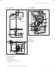
Boiler specifications 2 2.1.2 Dimensions 2.1.3 Installation 5 161 113 160 1 53 2 610 4 30 133 7 56 3 Fig. 2.2 Function elements of boiler 375 26 1 2 3 4 5 6 7 6 48 33 Flue pipe connection Fan Gas valve Electronics box Burner module Ignition electrode Condense trap 340 176 8 Fig. 2.
3 General requirements 3 General requirements 3.1 Preliminary remarks This appliance must only be installed and commissioned by a suitably competent person. Please check with your installer that he is able to carryout all the necessary works including official notification of the works to the relevant body upon completion. 3.
General requirements 3 tions in timber framed and light steel framed buildings“. Please note the safety instructions below before deciding where to install the boiler: 667 Caution! a Do not install the appliance in rooms prone to frost. In rooms with aggressive steam or dust, the appliance must be operated independent of the ambient air. Fig. 3.1 Art. No.
3 General requirements Terminal position A B C D E F G H I Fig. 3.5 Vertical Flue System Art. No. 30 32 00 3.5.1 Flue termination The following details refer to both flue systems. a. The terminal must be located where the combustible substances can escape freely at all times. b. A plume of water vapour will sometimes be visible from the flue terminal. Positions where this could be a nuisance should be avoided. c.
General requirements 3 3.9 Condensate drain A plastic drain pipe must be fitted to allow discharge of condensate to a drain. Condensate should, if possible, be discharged into the internal household draining system. If this is not practical, discharge can be made externally into the household drainage system or a purpose designed soak away, see Section 4.3.5 for more details. Fig. 3.7 Flue termination under balcony/eves 3.5.
3 General requirements 3.15 Cleanser and inhibitor In the case of an existing installation, it is essential that prior to installing the new boiler the system is thoroughly flushed. For optimum performance after installation of a new system, the boiler and its associated central heating system should also be flushed. Flushing should be carried out in accordance with BS7593: 1992 using a cleanser.
Low-salt saline Electric conductivity μS/cm at 25 °C < 100 100-1500 Appearance Free of sedimentary substances pH-value at 25 °C 8,2-10,01) 8,2-10,01) < 0,1 < 0,02 Oxygen Unit mg/L 1) With aluminium and aluminium alloys, the ph value range is restricted from 6.5 to 8.5. Table 3.
3 General requirements 3.18 Sealed water systems The installation must comply with the appropriate requirements of the current issue of BS4814, BS5449, BS6759, BS6798 and BS7074 Part 1 and 2. For IE your attention is drawn to the current edition of IS 813. It is highly recommend to use the Vaillant Sealed System Kit Article; 020053207 This includes all necessary components and is included in your Vaillant warranty. See also fig 3.10.
General requirements 3 3.18.5 Filling a sealed water system Provision for filling the system at low level must be made. This can be achieved by the use of a proprietary filling loop. 3 litres (o.
4 Boiler installation sequence 4 4.1 Boiler installation sequence Boiler location Note! h This boiler is not suitable for outdoor installation. This boiler may be installed in any room, although particular attention is drawn to the installation of a boiler in a room containing a bath or shower where reference must be made to the relevant requirements. This boiler is suitable for installation in bathroom zone 2. 4.1.
Boiler installation sequence 4 h Note! Care should be taken not to scratch the white slowly move downwards until engaged in the hanging bracket. 4.2 Flue exit Refer to flue system installation instructions for full details. 4.3.2 Removing the front casing Remove the front casing securing screws then lift the case upwards off the two top retaining dowels, see fig 4.4. surface of the boiler casing. Danger! d Vaillant appliances are certified only for use with ge-nuine Vaillant flue pipes.
4 Boiler installation sequence h Note! Ensure the gas supply pipe work is adequately sized so that a 20 mbar gas pressure is available at the boiler inlet at full flow rate. • Tighten all connections. • Check the gas connection with leak indicator spray for leakage. The gas supply can be connected from below, or through the wall at the rear of the boiler. See fig 4.5. and refer to section 3.4.
Boiler installation sequence 4 4.3.6 Installing the flue system • Install the flue system (refer to the separate air/flue duct installation instructions). 4.4 Electrical connections Danger! e This appliance must be earthed. Electrocution caused by touching live parts can be fatal. Before working on the appliance, turn off the power supply and secure against restart. • The boiler must be earthed. • All system components shall be of an approved type and all wiring to current I.E.E. wiring regulations.
4 Boiler installation sequence 4.4.2 Wiring system • Connect the mains supply to the terminal block, see fig 4 .8.1 the pump can be connected directly to the terminal block or alternatively as shown in diagram 4.8.2 . h Note! • Ensure that the wires are securely fixed in the terminal block. • Refit the electronics box cover by pushing into place until it clips back into position. • Raise the electronics box.
Boiler installation sequence 4 4.4.3 Electrical board layout eBUS accessory connection X20 X31 Burner cable harness X40 Accessory module connection Diagnosis via eBUS vrnet DIALOG X2 X41 ext. flow or return probe outer probe ext.
4 Boiler installation sequence NTC return NTC flow Ignition electrode X 20/5 red black link X 20/7 black Fan unit X 20/8 blue X 20/16 blue (earth) X 20/4 grey (PWM) X 20/3 black (hall signal) X 20/17 red (24 Vdc) Gas valve assembly X 20/18 red (24 Vdc) X 20/9 blue (earth) green/ yellow Chassis earth red red X20 black Electronic control box pump connection fuse T2E 250 Volts X2 bus 24 V 230 V green/yellow green/ yellow Fig. 4.
Boiler installation sequence 4 4.4.4 Controls Controls Article no. Installation VRT 392 Programmable Room Control 0020028509 Wall mounted VRT 392f RF Programmable Room Control 0020028514 Wall mounted VRC 470 Weather Compensator 0020108130 Wall mounted or plug in VRC 470f Weather Compensator (From Q3 2011) 0020108137 Wall mounted Accessories Article no.
4 Boiler installation sequence 4.4.6 Connection details for external switches and boiler terminal strip.
Commissioning (Part I) 5 5 Commissioning (Part I) Please ensure the “Benchmark” commissioning check list is completed and left with the user. 5.1 Preliminaries - all systems A competent person approved at the time by the Health and Safety Executive should carry out commissioning, in accordance with the current issue of BS 6798. • Remove the two screws on the inner case then lift the case upwards off the two top retaining dowels. • Drop down the electronics box into the service position.
5 Commissioning (Part I) 5.1.2 Gas pressure statement - Natural gas Natural gas: a Do not proceed with the adjustment or attempt to put the unit into service if the inlet working pressure lies outside the range shown in table 5.1 The nominal operating pressure at the gas meter outlet should be between 19 and 23 mbar. The gas valve within the appliance is factory set for Natural Gas G20 and should need no adjustment.
Commissioning (Part I) 5 In the unlikely event that a problem occurs with the operation of the ecoTEC boiler, the following points should be checked: Boiler fails to operate: – Is the gas supply turned on? – Is there enough water in the heating system? – Is the electrical supply switched on? – Is the control knob (1, fig 5.4) in the operating position? – Is there an ignition problem? Caution! a Inappropriate modifications can cause damage.
6 Natural gas to LPG conversion 6 Natural gas to LPG conversion The ecoTEC plus is able to be field adjusted for use on LPG – propane G31 gas. To enable conversion the use of a flue gas analyser is necessary. a Caution! After converting from natural gas to LPG, commission and check boiler function as described in commissioning section of the servicing and installation instructions.
Functional checks commissioning (Part II) 7 7 Functional checks commissioning (part II) 7.1 Functional checks After installing and checking the gas supply pressure, perform a function check before commissioning the appliance and handing over to the user. • Commission the appliance according to the relevant operating manual. • Check the gas supply pipe, flue system, heating system and the hot water pipes for leaks.
7 Functional checks commissioning (Part II) 8 Inspection and maintenance 7.6 Handing over to the user Inspection and maintenance Note! 8.1 the sticker supplied (835593) to the front case of the appliance in the user’s language. a Risk of injury and risk of damage to property h When you have finished the installation, attach h 8 Note! If fitted to a sealed system. • Set the maximum radiator temperature control to the desired setting.
Inspection and maintenance 8 We recommend the conclusion of an inspection and maintenance contract with an approved company or installer. The inspection serves to determine the actual condition of the respective boiler and compare it with the specified condition. This is done by measuring, checking and observing. Maintenance is required in order to eliminate any deviations of the actual condition from the specified condition.
8 Inspection and maintenance Overview of the inspection and maintenance tasks Maintenance must be carried out at regular intervals – but no longer than 5 years No. Activity Inspection must be carried out each year 1 Check the air flue gas installation for leaks and for proper fixation and ensure it is not blocked or damaged and is fitted correctly, complying with the relevant installation instructions. x x 2 Carry out a general inspection of the boiler for dirt and dust and clean as necessary.
Inspection and maintenance 8 8.1.4 General flue gas analysis point combustion air analysis point retaining dowel (2 off) retaining dowel (2 off) inner case front casing screw (2 off) chassis panel screw (2 off) screw (4 off) electronic box Fig. 8.1 Panels All routine servicing requirements can be achieved by the removal of the front casing, inner case and chassis panel only. • Remove the two screws on the underside of the front casing and lift off.
8 Inspection and maintenance 8.1.5 Spark electrode • Disconnect the ignition lead and earth lead from the igniter unit and two securing screws at the spark electrode. • Withdraw the spark electrode carefully from the combustion chamber, see fig 8.4. • Inspect the tips for damage. • Clean away any debris and check the spark gap is 3.5 -4.5 mm. • Check the electrode gasket for signs of damage and replace if necessary. Note! h • Do not disconnect at the gas valve.
Inspection and maintenance 8 • Clean the burner with a soft brush taking great care not to damage the front insulation. DO NOT use wire or sharp instruments to clean the holes of the burner. • Inspect the burner for any signs of damage. • Remove and discard the burner door seal and replace with new, see fig 8.7. 8.1.7 Combustion chamber and heat exchanger insulation Removal of the burner is not necessary during a normal service.
8 Inspection and maintenance 9 Combustion analysis • Remove valve cap from expansion vessel charge point. • Check that the internal charge pressure of the expansion vessel is to the correct design pressure. If the pressure is lower than this the vessel should be re pressurised using an air pump. • Refit the valve cap. • Re pressurise boiler and heating system. 8.1.11 Re commissioning the boiler • Carry out electrical safety checks. • Turn on the electrical supply. • Open the boiler CH service valves.
Combustion Analysis 9 Nat. Gas Model G20 % CO2 after 5 mins at full load LPG Maximum G31 % CO2 after 5 mins at full load Throttle Maximum Case off Case on CO/CO2 ratio Case off Case on Adjustment CO/CO2 ratio ecoTEC plus 415 9.1 + 0.2 - 0.5 9.3 + 0.2 - 0.5 <0.0026 10.1 + 0.5 - 0.5 10.3 + 0.5 - 0.5 5 turns <0.0026 ecoTEC plus 418 9.1 + 0.2 - 0.5 9.3 + 0.2 - 0.5 <0.0026 10.1 + 0.0 - 1.0 10.3 + 0.0 - 1.0 5 turns <0.0026 ecoTEC plus 428 9.1 + 0.2 - 0.5 9.3 + 0.2 - 0.5 <0.
10 Troubleshooting 10 Troubleshooting Display Meaning Heating mode (all models) 10.1 Logical fault finding procedure These checks must be carried out before attempting to use the fault finding guide. 1. Carry out electrical safety checks (see section 4 ‘Wiring system’). 2. Check that the external electricity supply to the boiler is on, and a supply of 230 V~ is present between boiler terminals ‘L’ and ‘N’. 3.
Troubleshooting 10 Caution! a Access to the second diagnostic level must be • Do not press any key for approx. 4 minutes. The current heating flow temperature appears in the display again. used exclusively by a qualified technician. First Diagnostic level • Press the “i” and “+” keys simultaneously. The display shows “d.0”. • Use the “+” or “–” keys to scroll through the desired diagnostic numbers of the first diagnostic level (see table 10.2). • Press the “i” key.
10 Troubleshooting Display Meaning Display value/adjustable value d.17 Heating flow/return regulation change over 0 = flow, 1 = return (factory setting: 0) d.18 Pump mode (return) 0 = return, 1 = nonstop, 2 = winter (factory setting: 0) d.19 Operating modes of the two-speed heating pump d.
Troubleshooting 10 10.1.3 Fault codes Fault codes take priority over all other display functions in the event of a system fault occurring.If multiple faults occur, the corresponding fault codes are displayed alternately for about two seconds each. 10.1.4 Fault memory The fault memory stores details of the ten most recent faults. Code Meaning F. 0 Flow–NTC open circuit F. 1 Return–NTC open circuit • Press the ”i” and ”–” buttons simultaneously.
10 Troubleshooting 10.2 Test programs Special functions can be triggered on the appliances by activating various test programs. These programs are given in detail in the Table 10.5. • The test programs P.0 to P.6 will be started when “Power ON” is turned on and the “+” key is pressed for 5 s. The display shows “P.0”. h Note! If the power switch is out of reach, alternativethen hold the "+" ly press the reset button key until "P0" is displayed.
Parts replacement 11 11 Parts replacement The tasks listed below in this section may be carried out only by a competent person approved at the time by the Health and Safety Executive as stated in the Gas Safety (Installation and Use) Regulations 1998.. • Only use genuine spare parts for repairs. • Make sure the parts are correctly fitted and that their original position and alignment are retained. 11.1 11.4 Replacing the fan • Remove the gas valve refer to section 11.3.
11 Parts replacement • Remove the clip securing the clear condense pipe to heat exchanger. • Pull to remove clamps (two at the top and one at the bottom) to remove the heat exchanger, see fig 11.2. h Note! There will be water in the heat exchanger. • Remove clear condense pipe connector from bottom of heat exchanger. 11.6 Replacing the condense trap and siphonic drain Note! h If a replacement trap is required remove spigot bung before fitting condensate drain connection.
Recycling and disposal 12 Factory guarantee and Vaillant service 13 12 Recycling and disposal The design of all Vaillant products takes into account the subsequent recycling and/or eventual safe scrapping of each component used. Vaillant’s in–house rules set strict standards in this respect. The selection process used for choosing raw materials includes full consideration of their recycling characteristics, and of the breakdown and separation properties of sub assemblies.
14 Appendix 14 Appendix 48 Instructions for installation and servicing ecoTEC plus 0020020828_07
Installation, Commissioning and Service Record Instructions for installation and servicing ecoTEC plus 0020020828_07 49
Please affix the label from the rear cover of the control box over this area.
SERVICE INTERVAL RECORD 0020008345-06 It is recommended that your heating system is serviced regularly and that you complete the appropriate Service Interval Record Below . Service Provider. Before completing the appropriate Service Interval Record below, please ensure you have carried out the service as described in the boiler manufacturer’s instructions. Always use the manufacturer ‘s specified spare part when replacing all controls.
0020020828_07 GBIE 042012 — Subject to alterations