For the heating engineer Installation instructions geoTHERM Heat pump VWS/VWW GB
Contents Contents 1 1.1 1.2 1.3 1.4 1.5 Notes on the documentation........................... 3 Storage of the documents ...................................... 3 Symbols used ............................................................. 3 Applicability of the manual..................................... 4 CE label ........................................................................ 4 Intended use ............................................................... 4 2 2.1 2.2 2.3 2.3.1 2.3.2 2.
Contents Notes on the documentation 1 8.10 Parameters that can be set with 1 Notes on the documentation vrDIALOG 810/2 ......................................................................... 66 9 9.1 9.2 9.3 9.4 Inspection and maintenance ........................... 68 General notes ............................................................. 68 Inspection work to be performed ......................... 68 Servicing and repairs ...............................................
1 Notes on the documentation 1.3 Applicability of the manual These installation instructions apply exclusively to appliances with the following part numbers: Type name Brine/Water Heat Pumps VWS 61/2 VWS 81/2 VWS 101/2 VWS 141/2 VWS 171/2 Water/Water Heat Pumps VWW 61/2 VWW 81/2 VWW 101/2 VWW 141/2 VWW 171/2 Article number 0010002778 0010002779 0010002780 0010002781 0010002782 0010002789 0010002790 0010002791 0010002792 0010002793 Table 1.
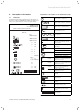
Description of the device 2 2 Description of the device Explanation of the symbols on the identification plate 2.1 Data badge An identification plate is attached to the baseplate on the inside of the geoTHERM heat pump. The type designation is located at the top of the grey pillar frame. Rated voltage - compressor Rated voltage - pumps + controller Rated voltage - auxiliary heating Vaillant GmbH Remscheid / Germany Serial-No.
2 Description of the device 2.2 Functional principle Heat pump systems consist of separate circuits in which liquids or gases transport the heat from the heat source to the heating system. As these circuits operate with differing media (brine/water, coolant and heating water), they are coupled to one another by means of heat exchangers. In these heat exchangers the heat passes from a medium at a high temperature to a medium at a lower temperature.
Description of the device 2 These different temperatures are produced in the coolant circuit by means of a compressor (2) and an expansion valve (4), which are situated between the evaporator and the condenser. The coolant flows in vapour form from the evaporator into the compressor, where it is compressed. This causes the pressure and temperature of the coolant vapour to rise sharply. After this process it flows through the condenser, where it releases its heat to the heating water by condensation.
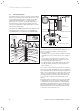
2 Description of the device 7 6 1 2 3 2.3.1 Component groups - VWS 16 1 5 2 4 3 4 5 6 15 7 14 8 9 Fig. 2.5 Rear view VWS/VWW 13 10 12 Key to Fig. 2.5 1 Return to domestic hot water cylinder 2 Heat source to the heat pump 3 Heat source from the heat pump 4 Transportation handles 5 Cable feedthrough for electrical connections 6 Heating return 7 Heating feed 8 11 Fig. 2.6 VWS - Front view, covers removed Key to Fig. 2.
Description of the device 2 2.3.2 Component groups - VWW 16 2.4 1 2 3 4 5 6 15 7 General notes on operating modes and functions There are five operating modes available for the heating circuit and these can be used for time and temperature control of the heat pump (see Chap. 8 "Control system"). There are a further three operating modes available for the integrated domestic hot water cylinder.
2 Description of the device 3 Safety instructions and regulations Additionally, there are further settable auxiliary functions available (see also Chap. 8.
Safety instructions and regulations 3 3.2 Regulations, rules, guidelines 3.2.1 Preliminary remarks for room sealed appliances This appliance should only be installed in conjunction with either a Vaillant flue system or an alternative approved system (details of flue approval categories can be found in the technical section of the installation manual). Install the flue system as detailed in the separate flue installation instructions supplied with this boiler. 3.2.
4 Assembly and installation 4 4.1 Assembly and installation Accessories h Note! Please see current price lists for information on possible necessary accessories. You can fit the following accessories to expand the heat pump system. You can find more detailed information on the installation of accessories in Chap. 6.9. Mixer module VR 60 With the mixer module, you can expand the control system of the heating installation by two mixer circuits. You can connect a maximum of six mixer modules.
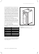
Assembly and installation 4 4.3 Dimensions and clearances 1200 600 0-10 1) 650 835 140 140 75 100 75 600 Fig. 4.
4 Assembly and installation 4.5 Preparatory work in the installation area 300 mm 10 mm 1 3 300 mm 2 300 mm 1 3 Fig. 4.3 Preparatory work in the installation area 600 mm Fig. 4.2 Minimum clearances for installing the heat pump 4.4 Assembly/Installation at a glance – Remove packing material. – Remove transportation safety devices. – Transport the heat pump to the installation area. – Position and align the heat pump in the intended assembly location. – Remove the upper cladding.
Assembly and installation 4 4.6 Requirements of the heating circuit The heat pump is only suitable for connection to a closed central heating installation. To ensure troublefree operation, the central heating installation must have been installed by authorised specialists in compliance with the applicable regulations. A heat pump is suited to low temperature heating systems. The system must therefore be designed for low flow temperatures (ideally around 30 to 35 °C).
4 Assembly and installation Pos. Amount 1 2 3 1 1 3 2 3 2 4 1 5 6 7 8 9 1 4 1 5 1 10 1 11 12 1 1 13 14 5 2 Description Heat pump Operating console, pillar cover Gaskets (yellow/green) for heating circuit elbow unions M6 flat-headed screws for fitting the operating console to the frame (plus one spare screw) Self-tapping screws for the operating console frame (incl. one spare screw) Self-tapping screws for fastening the vrnetDIALOG unit 6 Litre brine expansion tank incl. brass adapter, max.
Assembly and installation 4 We recommend that the heat pump be transported with the aid of a suitable barrow. 4.10 Installing the heat pump < 45° 0-10 mm Fig. 4.8 Adjusting the feet • Pay attention to the minimum wall clearances when installing the heat pump (see Fig. 4.2). • Align the heat pump horizontally by adjusting the feet. Fig. 4.
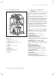
4 Assembly and installation 4.11 Removing the cladding The cladding panels are screwed on and additionally provided with retaining clips. Fig. 4.10 Removing the front lower cladding • Unfasten the two screws on the console frame and pull it, together with the front lower cladding, away from the casing. Fig. 4.9 Removing the upper cover • Remove the pipe access cover, which is fastened with retaining clips, by pulling it gently upwards.
Assembly and installation 4 4.12 On-site installation a Caution! Flush the heating system thoroughly before connecting the appliance! By doing that, residue such as welds, cinder, hemp, putty, rust, rough dust and similar substances are removed from the pipes. Otherwise such substances can be deposited in the appliance and cause damage. a Caution! To prevent leaks, take care that no mechanical stresses are created on the connection lines! 1 2 3 4 5 7 6 Fig. 4.
4 Assembly and installation 4.12.1 Assembly of the heating system 42a a Caution! Risk of damage! In order to be able to clear any possible overpressure, the heat pump must be connected to an expansion vessel and an expansion relief valve, at least DN 20 with a maximum opening pressure of 3 bar (not supplied). H Danger! Risk of scalding! The blow-off line on the expansion relief valve must be the size of the valve's outlet aperture and be installed in a frost-free environment.
Assembly and installation 4 Filling the heating and heat source systems 5 4.12.3 Assembly of the well system (VWW only) a Caution! Risk of damage! Make sure that no negative pressure can arise in the lines during operation and after the well pump has been switched off. The flexible hoses within the heat pump can be damaged as a result of negative pressure in the lines. With water as the heat source, the well system is in most cases implemented with a suction and injection well.
5 Filling the heating and heat source systems 5.2 Filling the brine circuit (VWS only) The brine fluid consists of water mixed with a heat transfer fluid concentrate. As an additive we recommend propylene glycol (alternative: ethylene glycol) with corrosion-inhibiting additives. A DN 40 collector hose has a capacity of approx. 1 litre per continuous metre. The brine fluids that may be used differ greatly from region to region. Please find out about this from the authorities responsible.
Filling the heating and heat source systems 5 To fill the brine circuit, proceed as follows: • Mix the antifreeze used by Vaillant in Germany, Austria and Switzerland, 1.2 % propylene glycol, with water in the proportion 1 : 2. This offers frost protection down to -15 °C. • Mix water and antifreeze to the specified concentration in an external container (e.g. plastic canister, see Fig. 6.1, Item. 66). Every batch of the mixture must be carefully blended. • Check the mixing proportions of the brine fluid.
6 Electrical installation 6 6.1 Electrical installation Safety and installation information e Danger! Risk of electric shock! Always switch off the power supply before carrying out any electrical installation work. Make sure that it is secured against inadvertent switching on again. a Caution! Risk of damage! The electrical connection must be equipped with a customer-supplied isolation device having a contact separation of at least 3 mm on all lines (e.g. a line protection switch).
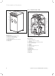
Electrical installation 6 6.3 Electrical control box 1 6 2 5 3 4 Fig. 6.1 Electrical control box Key to Fig. 6.
6 Electrical installation 6.4.1 Unblocked mains supply (Electroplan 1) 1 + + + (VWW) PE N L3 L2 L1 400 V / 50 Hz PE N L3 L2 L1 N L3 L2 L1 PE N N L3 L3 L2 L1 PE N L3 S S A Z N PE Fig. 6.2 Unblocked mains feed (supplied configuration) Key to Fig. 6.2 Pump Compressor Controller Auxiliary heater Heat source circuit This is how the heat pump is wired when delivered. The heat pump is connected to the mains on a single tariff (one consumer meter) (1).
Electrical installation 6 6.4.2 Dual circuit feed, heat pump tariff (Electroplan 2) 2 1 + + 400 V / 50 Hz (VWW) 400 V / 50 Hz 3 PE N L3 L2 L1 PE N L3 L2 L1 N L3 L2 L1 PE N N L3 L3 L2 L1 PE N L3 S S A Z N PE Fig. 6.3 Dual circuit feed, heat pump tariff Key to Fig. 6.3 Pump Compressor Controller Auxiliary heater Heat source circuit In this instance the heat pump is operated on two tariffs (two consumer meters).
6 Electrical installation 6.4.3 Dual circuit feed, special tariff (Electroplan 3) 2 1 + + (VWW) 230 V / 50 Hz 400 V / 50 Hz 3 PE N L3 L2 L1 PE N L3 L2 L1 N L3 L2 L1 PE N N L3 L3 L2 L1 PE N L3 S S A Z N PE Fig. 6.4 Dual circuit feed, special tariff Key to Fig. 6.4 Pump Compressor Controller Auxiliary heater Heat source circuit In this instance the heat pump is operated on two tariffs (two consumer meters). A permanent supply (2) for the secondary consumers (circulation pumps, controller, etc.
Electrical installation 6 6.4.4 Connecting external components 1 2 3 p (VWW) PE N L3 L2 L1 (VWS) PE N L3 L2 L1 N L3 L2 L1 PE N N L3 L3 L2 L1 PE N L3 S S A Z N PE Fig. 6.5 Connecting external components Key to Fig. 6.5 Pump Heat source circuit p Brine Switch 3-way valve with solenoid Only if the VPA Multi-cylinder or some other multicylinder is installed • Connect the external 3-way valve for the multi-cylinder to the terminals (3).
6 Electrical installation Controller PCB at a glance 1 2 L N ZH Zu Auf N LP/UV 1 3 L N ZP 4 L N SK2-P 5 L N HK2-P 6 Zu Auf N HK2 7 1 2 VF2 8 1 2 RF1 1 2 VF1 9 1 2 SP 10 11 12 + - 6.6 DCF OT AF BUS DCF/AF 1 2 EVU 13 14 1 2 1xZP 15 16 17 18 19 20 21 22 1 N L 2 N L 3 N L 4 N L 6 7 8 ASB L N 2 1 L N 2 1 5 SCH N L 2 1 23 33 32 31 30 29 28 27 26 25 24 Fig. 6.6 Controller PCB Key to Fig. 6.
Electrical installation 6 6.7 Wiring the controller PCB The controller has an automatic sensor recognition function. You must configure the connected heating circuits in accordance with the system combination. In the following you will find various options for operating the heat pump. 6.7.1 Connecting the VR 10 standard sensor Additional sensors are required as flow, return, collector or cylinder sensors, depending on the configuration of the system.
6 Electrical installation 6.7.2 Direct heating operation (Hydraulic plan 1) The heat pump is connected directly to the underfloor heating circuit. Control is carried out using energy balance control by default (see Chap. 8.4.2). To do this, the VF2 flow temperature sensor must be connected (floor protection circuit). 16 AF 42a VF2 30 30 31 31 WQ 30 VF2 32 31 27 33 39 400 V 400 V 42b Fig. 6.8 Hydraulic plan 1 Key 16 30 31 32 33 42a 42b 43 VF2 WQ to Fig. 6.
Electrical installation 6 6.7.3 Mixer circuit with buffer cylinder (Hydraulic plan 2) The unregulated underfloor heating circuits are operated by the external heating circuit pump from the buffer cylinder via a mixer. The flow temperature sensor sits behind the external pump. The heat pump responds to a demand for heat from the buffer cylinder. 16 AF 42a VF2 46 M VF1 30 30 31 31 27 WQ RF1 400 V 400 V 33 32 42b Fig. 6.9 Hydraulic plan 2 Key to Fig. 6.
6 Electrical installation 6.7.4 Direct heating operation and domestic hot water cylinder (Hydraulic plan 3) The heat pump is connected directly to the underfloor heating circuit. Control system is carried out using energy balance control by default (see Chap. 8.4.2). The VF2 flow temperature sensor must be connected (floor protection circuit). The heat pump also supplies a domestic hot water cylinder. 16 AF 42a 30 30 31 31 VF2 WQ 33 30 27 42b 400 V 400 V 31 VF2 32 39 25 SP 43 KW Fig. 6.
Electrical installation 6 6.7.5 Mixer circuit with buffer cylinder and domestic hot water cylinder (Hydraulic plan 4) The unregulated underfloor heating circuits are operated by the external heating circuit pump from the buffer cylinder via a mixer. The flow temperature sensor sits behind the external pump. The heat pump responds to a demand for heat from the buffer cylinder. 42a 46 27 30 30 31 31 VF2 M VF1 AF 32 WQ 33 55 42b RF1 400 V 400 V 30 SP 25 43 KW Fig. 6.
6 Electrical installation 6.7.6 Cooling Cooling mode is only possible when using the VWZ NC 14/17 accessory, and only for VWS 14 and VWS 17 heat pumps. More detailed information about this can be found in the installation manual for the VWZ NC 14/17 accessory. Information regarding the hydraulic plans can be found in the installation manual for the VWZ NC 14/17 accessory. 6.8 The structure of the Vaillant system allows you to run the eBus from component to component (see Fig. 6.13).
Electrical installation 6 6.9.2 Connecting further mixer circuits Like the VR 90 remote control units, the VR 60 mixer modules also communicate with the heating controller via the eBUS. When installing, observe the same procedure as for connecting the remote control units (see Chap. 6.9.1). The configuration of the system can be seen in Fig. 6.15. Pay attention to the installation manual for the expansion module. 6 1 5 4 2 3 Fig. 6.17 Connecting vrnetDIALOG Fig. 6.
6 Electrical installation 6.10 Connecting an external boiler If your external boiler has a Vaillant eBUS interface, you can connect it to the heat pump eBUS via the VR 32 accessory (see also the VR 32 manual regarding this). In both cases, the heat pump switches in the external boiler depending on the heat demand and the controller setting. To do this, set the hydraulic connection in Menu C8 "Auxiliary heater 1". 6.
Electrical installation 6 e Danger! Risk of electric shock! If the vrnetDIALOG accessory is not being used or does not receive its power supply from the heat pump, the vrnetDIALOG connecting plug (230 V supply) must remain secured inside the heat pump. Fig. 6.23 Fitting the upper cover Fig. 6.22 Fitting the front lower cladding • Attach the upper cover and screw it down securely with the two associated screws. • Press the pipe access cover into the spring retainer.
6 Electrical installation Fig. 6.24 Fitting and connecting the operating console • Connect the connecting cable to the operating console. Fig. 6.25 Fitting the front panel of the operating console • Insert the front panel of the operating console into the spring retainer on the console frame.
Start-up 7 7 Start-up d Danger! Risk of injury! The heat pump may only be put into operation after all the cladding sections have been fitted. 7.1 General points regarding start-up • Before putting the heat pump into operation, first check the Start-up Checklist in Chap. 14. The heat pump may only be started if all the points noted there have been satisfied. Before you actually start up the heat pump, familiarise yourself with the controller interface described below. 7.2 Operating the controller 7.
7 Start-up 7.2.2 Calling up the screens The menus are identified by a number at the top right of the display. You can access the next menu by turning the dial. The numbers make it easier to find individual menus during programming. 7.2.3 Typical operating sequence on the operator level Vaillant Loading... Fig. 7.2 Controller being initialised • Turn the dial until the required menu is selected. • Turn the dial until the parameter to be changed is selected.
Start-up 7 • Turn the dial until the hydraulic plan matching your system has been selected (see Table 7.1). You will find the hydraulic diagram for your installation in Chap. 6.7.2 ff. • Press the dial to confirm the selection. Installation completed 1 2 X X AF, VF2 X Fig. No. Probe DHW cylinder CH circuit X 3 4 >yes Fig. 7.5 Menu A9: Ending the installation Buffer tank Hydraulic plan No. Exit mode? >Values can be set A9 6.8 AF, VF1, VF2, RF1 6.9 X X AF, SP, VF2 6.
8 Controller 8 Controller To operate the heat pump economically, it is important to match the control system to the customer's heating system and to the pattern of use. In the following chapter, all the functions of the weather-controlled energy balance controller will be explained. 8.
Controller 8 Phase monitoring The sequence and presence of the phases (clockwise rotating field) of the 400 V supply are checked at the initial commissioning and continuously checked during operation. If the sequence is not correct or if one phase drops out, a fault-induced shutdown of the heat pump takes place to prevent damage to the compressor. Freezing protection function The outlet temperature of the heat source is measured continuously.
8 Controller When the function is started, the current time of the start is saved. The day is changed exactly at this time. After network-off/-on, the floor-drying begins as follows: Last day before mains off 1 - 15 16 17 - 23 24 - 28 29 Start after mains on 1 16 17 24 29 Table 8.
Controller 8 8.4.3 Buffer cylinder charging principle The buffer cylinder is controlled depending on the setpoint flow temperature. The heat pump heats when the temperature measured by the sensor at the top of the buffer cylinder, VF1, is lower than the setpoint temperature. It heats until the temperature measured by the sensor at the base of the buffer cylinder, RF1, has reached the setpoint temperature plus 2 K.
8 Controller 8.5 Operator level sequence diagram Reset to default settings Graphics display We 16.02.08 9:35 Factory setting Cancel Time programme Everything > Select > 5 sec. NO/YES NO/YES NO/YES Graphics display cooling* Installer Menu We 16.02.08 9:35 Sparen aktiviert for > 12:00 > Select stop time We 16.02.08 9:35 Party function enabled Energy input display We 16.02.08 9:35 One-time DHW tank loading enabled Mo 21.04.08 Flow Temp.
Controller 8 8.6 Code level sequence diagram Code layer change Code number: HK2 Parameters HK2 Switch-on room temp. Parameterss HK2 NoneRaumaufschaltung Parameterss Keine Raumaufschaltung Remote control Keine >Values can be set Fernbedienung C1 0000 Accept change? >Adjust numeric character No >Values can be set Fernbedienung >Values can be set Special function Floor drying HK 2 Parameters Type Heating curve Max limit outs.temp. Comp.
8 Controller Installation assistent Auxiliary heater Integration of the Auxiliary heater Out T. aux htr on A3 >intern -5 °C >Select Diagnosis Refrigerant circuit Test Comp High Pressure T outlet compresor Comp Low Pressure T inlet compressor D1 >no 11,9 bar 66 ºC 2,3 bar 0 ºC Error History I1 >1 96 Fault number Fault code 16.02.05 07:18 Refrigerant pressure sensors fault Installation assistent Geothermal settings Freeze protect Temp.
Controller 8 8.7 Displays in the operator level Display shown Description Graphics display (Top-level display) You can read off the instantaneous state of the system from this display. This will always be shown if you have not actuated either of the dials for a long time while another display is showing. Outside temperature (here 10 °C) Source inlet temperature: temperature sensor T3; 9 °C in the example (see Figs.
8 Controller Display shown Mo 21.04.08 Current flow temp. Description 16:49 1 28 °C CH pressure 1.2 bar Brine pressure 1.4 bar CH : comp. only. Warning message Warning message Energy input display Shows the energy extracted from the environment for each of the 12 months of the current year (black bar). White-filled bars represent the future months of the year; the height of the bar corresponds to the yield for the month in the previous year (to permit comparison).
Controller 8 Display shown Parameters Heating mode >Auto Set value day Night set back temp. Description The Set value day is the temperature at which the heating is to regulate in the "Heating" mode or during the time window. The set-back temperature is the temperature to which the heating is regulated during the set-back 22 °C period. Each heating circuit can be set to its own 15 °C set-back temperature. 2 Factory setting Set value day: 20 °C Set-back temp.
8 Controller Display shown 4 DHW Parameters Hot water mode >Auto Max. DHW temp. 60 °C Min. DHW temp. 44 °C Current DHW temp. Select flow temperature Time programme >Mo 1 00:00 24:00 2 : : 3 : : Description Factory setting The auto, on, and off operating modes are possible for the connected domestic hot water cylinders and the circulation circuit: Min. hot water temp.
Controller 8 Display shown Description Periods 1 >06.01.08 08.01.08 2 14.01.08 30.01.08 Room Temp. setpoint >Set starting day Basic data Date Day of week Time 21.04.08 Mo 09:35 It is possible to program two holiday periods by specifying the dates for the controller and all system components connected to it. In addition, you can set the desired target room temperature for holidays here, i.e.independently of the preset timer program.
8 Controller 8.8 Displays in the code layer The Code layer has different areas in which you can change parameters or merely view them, depending on the context. The context can always be recognised from the menu name. Menu C: Set parameters for the heating system Menu D: Perform diagnostics Menu I: Display general information Menu A: Installation Assistant Your code entry is reset again 15 minutes after your last change in the Code level (actuation of one of the dials).
Controller 8 Display shown Description C4 Information Setpoint flow temp. 41 °C Flow temp. VF2 30 °C Status of pump Off Actual °mins lag/gain -183 °min C4 Parameters Setpoint flow temp. 41 °C Flow temp. VF2 29 °C Status of pump Off Status hydr. mixer Open Parameters Switch-on room temp.
8 Controller Display shown Auxiliary heater Aux on during CH Aux on during DHW CH start at >Values can be set Description Factory setting Aux on during CH no CH: CH blocked. no CH comfort CH enabled, dependent on Out T. aux htr on no CH no CH and °mins lag/gain. comfort CH only: Heating mode by means of auxiliary heat-600 °min ing only, e.g. in emergency operation Hot water operation no CH: CH blocked comfort Auxiliary heating supplies the temperature level that the compressor cannot provide (approx.
Controller 8 Display shown Description Menu D: Perform diagnostics In Menus D1 to D5 you can operate and test the heat pump in diagnostic mode. The diagnostic menus cannot be exited with any setting apart from "Test = no" (Menu D1). An auto reset occurs 15 minutes after the last button is actuated. In the diagnostic mode, the pre-, minimum and run-on times of the compressor, pumps and other components are not heeded! Malfunctions can occur if the diagnostic mode is frequently turned on and off.
8 Controller Display shown Description diagnosis CH circuit D5 Buffer VF1 45 °C Buffer RF1 36 °C Sensor VF2 38 °C Current DHW temp. 52 °C HK Menu I: Display general information Error History Fault number Fault code 16.02.08 07:18 Error Error - sensor fault Buffer VF1: Buffer cylinder top temperature sensor Buffer RF1: Buffer cylinder base temperature sensor Sensor VF2: Current CH flow temperature Hot water SP: Temperature in the domestic hot water cylinder.
Controller 8 Display shown Menu A: Installation Assistant Installation Language selection Language Description Factory setting You will be guided through the Installation Assistant, Menus A1 and A2, during the initial commissioning of the heat pump. The Installation Assistant appears automatically during initial commissioning. Language: Set the local language A1 >GB english During the initial installation the controller always starts with this menu (Installation Assistant).
8 Controller Display shown Installation assistant Auxiliary heater integration of the Auxiliary heater WW+HK Out T. aux htr on >Values can be set Installation assistant Geothermal settings Freeze protect temp.
Controller 8 Display shown Description VR 60 Actuators Sensors Select The display only appears is several heating circuits and at least one VR 60 are installed. Addr. 4 You can check the actuators for the connected accessories with the component test 2. This intervenOff tion lasts for a maximum of 20 minutes and ignores 29 °C current controller inputs during this time. Afterwards, the heat pump reverts to its previous operating condition.
8 Controller 8.9 Installer Menu Special functions can be selected only from the basic display. To do so, press the left hand dial . To change the parameter, you must turn the dial. The following special functions can be selected: • • • • Energy saving function: Press dial once. Party function: Press dial twice. One-time charging: Press dial 3 x. Cooling: Press dial 4 x To activate one of the functions, you merely have to select it.
Controller 8 Display shown We 16.02.08 Description 9:35 Cooling function active for > 3 days This menu is only displayed when the heating system is fitted with an external cooling plant (accessory VWZ NC 14/17 ) and an appropriate hydraulic plan has been set. Cooling duration: OFF/1 to 99 days. If the cooling mode is active, a snowflake symbol appears in the graphics display. Table 8.5 Special functions (cont.
8 Controller 8.10 Parameters that can be set with vrDIALOG 810/2 Using its computer-supported graphics visualisation and configuration, vrDIALOG 810/2 (eBUS) enables you to optimise heating appliances and control systems and thus make use of their energy saving potential. Both of them enable you to create a visual impression of the processes in your control system and influence them at any time.
Controller 8 Parameters Description Factory setting Minimum flow temp. Maximum flow temp. Minimum/Maximum temperature: Setting the limiting temperatures (min. and max.) that the heating circuit can request. Together with the maximum temperature, the value for the floor protection switching is also calculated (max. HK temp. + Compr. hysteresis + 2K).
9 Inspection and maintenance 10 Troubleshooting and diagnostics 9 Inspection and maintenance 9.1 General notes In contrast to heaters based on fossil fuels, no expensive maintenance work is necessary for the Vaillant geoTHERM heat pump. However an annual inspection of the system by a specialist is a prerequisite for continuing operational safety, reliability and a long working life. d Danger! Inspection and repairs may be carried out only by an approved heating installation company.
Troubleshooting and diagnostics 10 – Temporary shut-down The heat pump remains in operation. The error is displayed and disappears independently when the cause of the fault is removed. – Fault-induced shutdown The heat pump is shut down. It can only be restarted by resetting the error after removing the cause of the fault (see Menu I 1). – In addition,other errors/malfunctions can occur on the unit or system. 10.
10 Troubleshooting and diagnostics 10.4 Temporary shut-down The compressor shuts down, the heat pump remains in operation. The compressor can start again after 5 minutes at the soonest. (see below for exceptions). Fault code Error text/description Possible cause Remedy 20 Heat source outlet frost protection monitoring Heat source pump defective, temperature sensor T8 or T3 defective. Too low a volume flow in the heat source circuit. No/full dirt filter in source return line. Air in brine circuit.
Troubleshooting and diagnostics 10 Fault code Error text/description 27 Coolant pressure too high 28 29 Possible cause Remedy Heat consuming side using too little heat. Possible causes: Air in the heating system. Bleed the heating system. The integral high pressure switch Defective heating pump or pump out- Check pump, replace if necessary. has tripped at 30 bar (g). put has reduced. Radiator heating without low loss Check the system. The heat pump can start again header or buffer cylinder.
10 Troubleshooting and diagnostics 10.5 Blocking error The heat pump is shut down. It can only be restarted by resetting the error after removing the cause of the fault (see Menu I 1). With the exception of Errors 90 and 91, these do not need to be reset. The heat pump starts again when the cause of the error has been removed.
Troubleshooting and diagnostics 10 Fault code Error text/description 60 Heat source outlet frost protection monitoring Emergency Possible cause mode possible Error 20 occurred three times in succession 61 VWW only Heat source outlet frost protection monitoring Heat source outlet frost protection monitoring No ground water flow Flow temperature too high for underfloor heating _ Flow temperature is higher than a preset value for 15 min (max. HK temp. + compr.hysteresis + 2 K) (see Chap. 8.
10 Troubleshooting and diagnostics Fault code Error text/description 91 Brine pressure too low Pressure < 0.2 bar Heat pump shuts down and goes into operation automatically when the pressure rises above 0.4 bar 94 Phase loss Check circuit breaker Emergency Possible cause mode possible Pressure drop in the heat source system as a result of leakage or air lock. Brine pressure sensor defective. possible One or more phases dropped out. 95 Wrong direction of rotation. Change comp.
Recycling and disposal 11 Customer service and guarantee 12 11 Recycling and disposal Both your Valliant geoTHERM heat pump and its associated packaging consist mainly of raw materials that can be recycled. 11.1 Appliance If your heat pump is identified with this symbol, it does not belong with your household waste at the end of its useful life. In this case, make sure that the Vaillant appliance and any accessories present are properly disposed of at the end of their useful life.
13 Technical data 13 13.1 Technical data Technical data - VWS Description Article number Height without connections Width Depth without pillars Depth with pillars Weight - with packaging - without packaging - ready for operation Rated voltage - Heating circuit/Compressor - Control circuit - Auxiliary heating Fuse, slow-blow Start-up current - without start-up current limiter - with start-up current limiter Electrical power consumption: - min. for B-5W35 - max.
Technical data 13 Description Internal sound level Conforms to safety regulations Unit dbA - VWS 61/2 46 VWS 81/2 48 VWS 101/2 VWS 141/2 50 52 CE mark Low Voltage Directive 73/23/EWG EMC Directive 89/336/EWG EN 60335 ISO 5149 VWS 171/2 53 Table 13.1 Technical data - VWS (cont) a 13.2 Caution! R 407 C is a chlorine-free coolant which does not affect the ozone layer. Nevertheless, any servicing work on the coolant circuit should only be carried out by authorised specialists.
13 Technical data Description refrigerant circuit - Coolant type - Quantity Unit VWW 61/2 VWW 81/2 VWW 101/2 VWW 141/2 VWW 171/2 kg 1.9 2.2 R 407 C 2.05 2.9 3.
Start-up checklist 14 14 Start-up checklist Check the following checklist before putting the heat pump into service. Only operate the heat pump when all points have been satisfied in essence.
14 Start-up checklist Water circuit checklist (VWW only) Was the water or its composition examined? Was a second heat exchanger used for decoupling? Was a dirt filter fitted at the water side input to the heat pump? Were isolating devices fitted ahead of the heat pump? Were the pipes thermally insulated against vapour diffusion? Electrical installation checklist Is there an isolation device with at least 3 mm contact opening fitted on the customer side and was it appropriately labelled? Were all electrical
Reference 15 15 Reference To the technician: Please fill in the following tables to facilitate any servicing work that may arise.
15 Reference Planning the heat pump installation Details Details regarding heat demand Heating load of the property Hot water supply Was a central DHW supply used? Was the user's behaviour regarding hot water demand taken into account? During planning, was the increased hot water demand of Jacuzzis and showers taken into account? Equipment used in the heat pump system Details Unit designations of the installed heat pump Details regarding the domestic hot water cylinder Domestic hot water cylinder type
Reference 15 Details for VWW Details Magnitude of the mass flow that can be extracted from the ground water/well Ground water pump type Details regarding the heat consuming system Details If a second pump was incorporated to overcome the pressure losses: Manufacturer and type of the second pump Heating load of the underfloor heating Heating load of the wall heating Heating load of the combination underfloor heating/radiators Was a secondary return installed? (Yes/No) Starting up the hear pump system D
Appendix Appendix Sensor characteristics VR 10 external temperature sensors VR 11 internal temperature sensors Temperature (°C) -40 -35 -30 -25 -20 -15 -10 -5 0 5 10 15 20 25 30 35 40 45 50 55 60 65 70 75 80 85 90 95 100 105 110 115 120 125 130 135 140 145 150 155 Temperature (°C) -40 -35 -30 -25 -20 -15 -10 -5 0 5 10 15 20 25 30 35 40 45 50 55 60 65 70 75 80 85 90 95 100 105 110 115 120 125 130 135 140 145 150 155 Resistance (ohms) 87879 63774 46747 34599 25848 19484 14814 11358 8778 6836 5363 4238 33
Appendix VRC-DCF outside temperature sensor Temperature (°C) -25 -20 -15 -10 -5 0 5 10 15 20 25 30 35 40 Resistance (ohms) 2167 2067 1976 1862 1745 1619 1494 1387 1246 1128 1020 920 831 740 Table 3, Appendix, VRC DCF sensor characteristics Installation instructions geoTHERM VWS/VWW 0020057444_01 85
Appendix Heat pump schematic - VWS 14 13 15 M T6 T5 1 2 T1 11 12 3 4 5 T4 T2 6 7 10 9 T8 T3 8 Fig. 1, Appendix, Heat pump schematic - VWS Key to Fig.
Appendix Heat pump schematic - VWW 15 14 16 M T6 T5 1 2 T1 12 13 3 4 5 T4 T2 6 7 11 9 10 T3 T8 8 Fig. 2, Appendix, Heat pump schematic - VWW Key to Fig.
N blue yellow-green grey L2 brown blue T3 black T2 yellow-green grey grey T1 grey brown Safety thermostat (STB) Links for starting current limiter A12-30-01 blue L3 L2 L1 L3 L2 L1 N L3 S S A Z N vrnetDIALOG (optional) L N ZP 2 N L 3 N L 4 N L L N SK2-P Fuse T4A/250 V Zu Auf N LP/UV 1 Heating pump 1 N L L N ZH 1 2 RF1 Phase monitoring 1 2 VF2 1 2 VF1 6 7 8 ASB L N 2 1 N L 2 1 Fuse T4A/250 V Zu Auf N HK2 5 SCH N L 2 1 L N HK2-P red red 1 2 SP Brine pump yellow
grey blue Installation instructions geoTHERM VWS/VWW 0020057444_01 T3 T2 yellow-green grey brown black brown Electric auxiliary heating T1 grey STB Links for starting current limiter black T2 T3 grey T1 A Z N 1 N L L N ZH 2 N L L N ZP L N SK2-P 3 N L Heating pump 4 N L Fuse T4A/250 V Zu Auf N LP/UV 1 vrnetDIALOG (optional) white white brown blue E 16 DU T3 N L3 1 2 RF1 1 2 VF1 Phase monitoring 1 2 VF2 Flow monitor yellow-green yellow-green 6 7 8 ASB L N 2 1 N L 2
0020057444_01 GB 072008