For the heating engineer/for the owner Operating and Installation Manual Mixer module VR 61 Mixer module for VRC 430 / VRC 430f VR 61 GB For latest prices and delivery to your door visit MyTub Ltd - 0845 303 8383 - www.mytub.co.uk - info@mytub.co.
Contents Contents 1 1.1 1.2 1.3 Notes on the documentation 3 Storage of the documents ....................................3 Symbols used ...........................................................3 Validity of the instruction manual ......................3 2 2.1 2.2 2.3 Description of the device ...............................4 Identification plate ..................................................4 CE-mark/conformity................................................4 Intended use ........................
Notes on the documentation 1 1 Notes on the documentation The following notes are intended to help you throughout the entire documentation. Further documents apply in combination with this operating and installation manual. We accept no liability for any damage caused by failure to observe these instructions.
2 Description of the device 3 Safety instructions and regulations 2 Description of the device The mixer module VR 61 is used for the system extension of the VRC 430 or VRC 430f regulators. Different configurations of heating system can be realised using the VR 61 mixer module. The four basic configurations correspond to the four hydraulic drawings, described in greater detail in Section 4 Incorporation of the VR 61 in the heating system.
Incorporation of the VR 61 in the heating system 4 4 Incorporation of the VR 61 in the heating system The application possibilities of the mixer module VR 61 are shown in the four hydraulic diagrams. In each case these are maximum configurations. Some of the components can be optional.
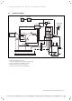
4 Incorporation of the VR 61 in the heating system 4.1 Hydraulic drawing 1 VR 81 VRC 430 230 V ~ AF (VRC 693, VRC 9535) VR 61 VRC 9642 VF 2 (VR 10) HK2-P HK2 VF 1 (VR 10) ZP HK1-P SP 1 (VR 10) Fig. 4.
Incorporation of the VR 61 in the heating system 4 4.2 Hydraulic drawing 2 VR 81 VRC 430 230 V ~ AF (VRC 693, VRC 9535) VR 61 VRC 9642 VR 40 VF 2 (VR 10) HK2-P VF 1 (VR 10) ZP HK2 HK1-P SP 1 (VR 10) LP Fig. 4.
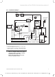
4 Incorporation of the VR 61 in the heating system 4.3 Hydraulic drawing 3 VRC 430 VR 81 VR 61 ZP SP 1 (VR 10) 230 V ~ VRC 9642 LP VF 2 (VR 10) HK2-P AF (VRC 693, VRC 9535) HK2 HK1-P Fig. 4.
Incorporation of the VR 61 in the heating system 4 4.4 Hydraulic drawing 4 VR 81 VRC 430 230 V ~ AF (VRC 693, VRC 9535) VR 61 VR 40 HK2-P HK1-P ZP SP 1 (VR 10) LP Fig. 4.
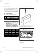
5 Assembly 5 Assembly 5.2 Assembling VR 61 mixer module The mixer module VR 61 is wall-mounted in proximity with the associated function units . The adjustment of all required parameters is carried out using the controller VRC 430 or VRC 430f via eBUS. All connections of the associated function units take place directly on the mixer module VR 16 via ProE terminals. 5.1 Scope of delivery Before starting the installation, check the scope of delivery for completeness and lack of damage. Pos.
Assembly 5 Electrical installation6 ⇒ ⇒ ⇒ ⇒ ⇒ Mark the two fixing points at a suitable position in accordance with the fixing openings (1). Drill two holes for the suitable plugs and screw the casing securely in position. The electrical installation is carried out as described in Chapter 6. Insert the casing cover back into the hinges and hinge the casing cover back up into position. Screw the casingcover in position in accordance with Fig. 5.1. 5.
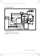
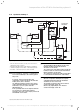
6 Electrical installation 1 VRC 430 3 VR 61 2 230 V~ Fig. 6.1 Connection of eBUS and mains cable in the system Key 1 Heating unit 2 230 V line from the user 3 eBUS connection (twin core) 230 V~ 5 V / 24 V 230 V~ ZP/LP HK1-P HK2 HK2-P BUS PE N L PE N L PE N L PE N Auf Zu PE N L + - VF2 2 1 M 1 2 3 6 5 7 4 Fig. 6.
Electrical installation 6 Start-up 7 h IfNote! a charging pump or circulation pump is connected, the configuration is carried out using the installation assistant of the controller VRC 430 or VRC 430f. 7 The commissioning of the mixwe module VR 61 is carried out in conjunction with the commissioning of the controller VRC 430 or VRC 430f. Proceed in accordance with the instructions in the manual of the VRS 430 or VRC 430f controller. 7.
7 Start-up – Display screen A3 If you wish to leave the installation assistant: ⇒ Installation assistant System configuration Relay output ZP/LP: A3 ⇒ ZP Turn the left hand adjuster of the controller VRC 430 VRC 430f in a clockwise direction to reach the display screen A6. Confirm the termination of the installation with "Yes".
Start-up 7 Display screen Title display screen adjustable operating values (just display = A) Remarks Unit Min. value Max. value C1 HC1 Information Feed set target (A) Flow temperature target value °C FBG connection / room actual value Remote control connected? Room actual display °C Yes, no and 0.
7 Start-up Display screen Title display screen adjustable operating values (just display = A) Remarks Unit Min. value Max. value Step width Preset value C9 HC1 parameters Set-back temperature For the times between the time windows you can set a set-back temperature. If your expert technician has set the frost protection function, the set-back temperature is automatically 5 °C.
Start-up 7 Display screen Title display screen adjustable operating values (just display = A) Remarks Unit Min. value Max. value Step width Preset value C11 HC2 parameters Set-back temperature For the times between the time windows you can set a set-back temperature. If your expert technician has set the frost protection function, the set-back temperature is automatically 5 °C.
7 Start-up Display screen Title display screen adjustable operating values (just display = A) Remarks C21 Total system parameters Mode Auto_OFF Determines the heating control outside the programmed time window Frost protection delay time Delay time of the start of the frost protection function or the ECO function. Hrs. 0 Max.
Start-up 7 VRC 430 / VRC 430f Operating level for the operator 8 7.3 8 Function floor drying The floor-drying function is used to “heat dry” a freshlylaid heating layer according to instructions. h Note! The floor drying function is only available for the controlled heating circuit (HC2) If this function is activated, all selected operating modes are stopped. The flow temperature of the controlled heating circuit is controlled according to a pre-set program regardless of the outside temperature.
8 VRC 430 / VRC 430f Operating level for the operator – Display screen 3 HC2 Time programmes 06 : 00 - 10 : 40 : : : : 9 HC2 parameters HC2 Parameter 3 HC2 Time programme Mo 1 2 3 – Display screen 9 Night set back temp. Heating curve 21.5 °C 15 . 0 ° C 1.2 > Select temperature > Select day of week Fig. 8.3 Display screen 3 Display/input time programmes for heating circuit 2 Fig. 8.
VRC 430 / VRC 430f Operating level for the operator 8 Display screen Title display screen adjustable operating values Remarks Unit Min. value Max. value (just display = A) 3 4 5 7 8 HC2 timer programmes Step distance Selection possibilities Preset value Day of week / week block Select single weekday or block of days (e.g.
8 VRC 430 / VRC 430f Operating level for the operator 9 Technical data Display screen Title display screen adjustable operating values Remarks Unit Min. value Max. value Step distance Selection possibilities Preset value Set-back temperature For the times between the time windows you can set a set-back temperature. If your expert technician has set the frost protection function, the set-back temperature is automatically 5 °C.
For latest prices and delivery to your door visit MyTub Ltd - 0845 303 8383 - www.mytub.co.uk - info@mytub.co.
0020044359_00 GB 042007 For latest prices and delivery to your door visit MyTub Ltd - 0845 303 8383 - www.mytub.co.uk - info@mytub.co.