Installation instructions For the heating engineer Installation instructions VRC 470f GB, IE
the nation’s favourite for PLUMBING & HEATING SUPPLIES FREE SHIPPING SECURE PAYMENTS on all orders over £100 to mainland UK shop online with confidence FINANCE AVAILABLE PRICE MATCH spread the cost with low interest rates always get the best deals available we have H U G E R E D U C T I O N S ON THOUSANDS OF ITEMS Boilers Bathroom suites Radiators Kitchen sinks & taps Heating controls Showers Pipes & ittings Wet rooms Cylinders Towel warmers Fires Bathroom furniture Renewable energy
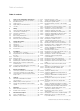
Table of contents Table of contents 1 1.1 1.2 1.3 1.4 1.5 Notes on the installation instructions ..............4 Observing other applicable documents ................4 Document storage ......................................................4 Symbols used ...............................................................4 Applicability of the instructions ..............................4 Glossary.........................................................................4 2 2.1 2.1.1 2.1.2 2.2 2.3 2.4 2.
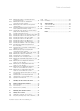
Table of contents 8.5.6 8.8 8.9 8.10 Defining the time for executing the antiLegionella function...................................................33 Defining the offset for charging the domestic hot water cylinder ..................................33 Defining the run-on time for the cylinder charge pump ..............................................................33 Activating parallel charging (domestic hot water cylinder and mixing circuit) ........................
1 Notes on the installation instructions 1 Notes on the installation instructions The following instructions are intended to guide you throughout the entire documentation. Further documents apply in combination with these installation instructions. We accept no liability for damage caused by failure to observe these instructions. 1.
Safety 2 2 Safety 2.1 2.2 Safety and warning information > When installing the VRC 470, take account of the basic safety instructions and the warning notes that may appear before an action. 2.1.
2 Safety Protecting against Legionella The controller is furnished with an anti-Legionella function to protect against infection by germs (Legionella). When the function is activated, the water in the domestic hot water cylinder is heated to over 60 °C for at least one hour. > Set the anti-Legionella function when installing the controller. > Explain to the operator how the anti-Legionella function works.
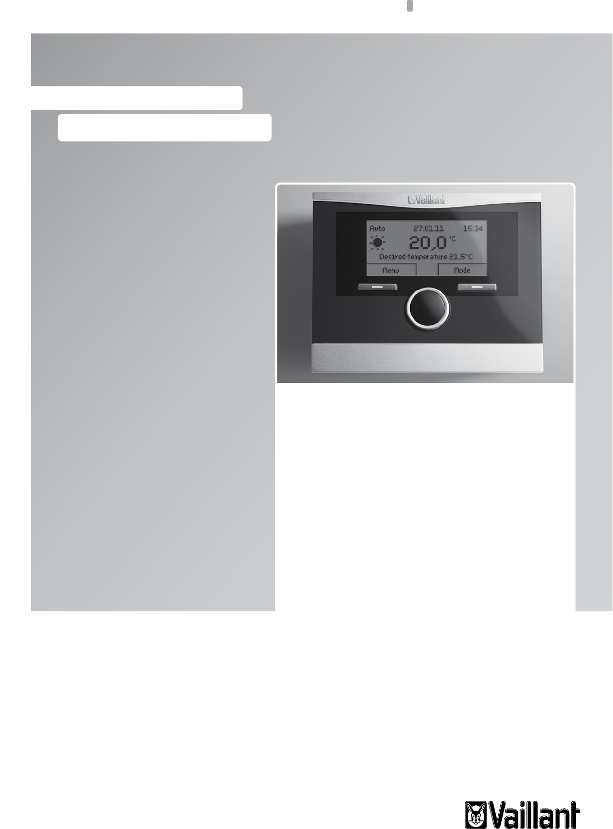
System description 3 3 System description 3.1 3.2 System design The VRC 470 controller controls the Vaillant heating system and hot water production. You can mount the controller on a wall using the wall mounting base or in the controller slot of a Vaillant boiler, without the wall mounting base. 1 2 3 Operation Heating installation The VRC 470 is a weather-compensated controller with a separate sensor.
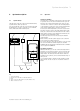
3 System description 3.3 3.4 Unit design Identification plate The identification plate is located on the rear side of the controller electronics (PCB) and is no longer accessible from the outside after the controller has been installed in the boiler or after it has been wall-mounted in the living area. 1 (21)092600200285150907011320N4 9 . . . 24V <50mA VRC 470 2 1 2 3 4 5 Fig. 3.
System description 3 Remote control unit VR 81/2 If the controller is installed in the boiler or if the second heating circuit is to be influenced decentrally, you can use the remote control unit VR 81/2. You can use the remote control unit VR 81/2 to set the parameter "Room temp. target". In addition, the controller displays service and fault messages by means of symbols. Data interchange is via eBus line.
4 Installation 4 Installation You can either integrate the controller within the boiler or install it separately on a wall in the living area. In the case of wall mounting, you connect the controller to the boiler via a 2-core eBUS line. > On building with up to three floors, install the external sensor (¬ Section 4.5) at 2/3 of the total wall height, and on buildings with more than three floors, install it between the 2nd and 3rd floors. 4.3 4.
Installation 4 If there are horizontal plug connections without pins on the control cabinet: 4.4 Mounting the controller in the living room 1 1 7 6 2 4 2 3 5 3 Fig. 4.1 4 Connecting the pin header > Connect the 3-way pin header supplied with the controller with the short ends in the 3 horizontal openings on the controller PCB. > Carefully push the controller with the pin header into the plug connection of the control cabinet. > If not already done, mount the external sensor (¬ Section 4.5).
4 Installation > Use the screws supplied to secure the wall mounting base. > Connect the eBUS cable to the terminals of the pin header (¬ Section 5.3). Installing the controller > Carefully insert the controller in the wall mounting base. Take care to ensure that the pin header (5) on the wall mounting base fits in the controller connector provided.
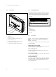
Installation 4 1 2 3 5 4 2 3 Fig. 4.4 Fitting the external sensor VRC 9535 1 2 3 4 5 Mounting holes Cap nut for cable entry point Connection cable with drip loop Wall mounting base Housing cover Install the external sensor as follows: > Mark the position on the wall. Observe the cable routing for the external sensor. > Route the connection cable (3) on-site with a slight incline to the outside and with a loop to catch drips. > Remove the casing cover (5) from the external sensor.
5 Electrical installation 5 Electrical installation e 5.1 Danger! Risk of death from live connections! When working in the control cabinet of the boiler there is a risk of death from electric shock. Continuous voltage is present on the mains connection terminals, even if the main switch is turned off! > Switch the main switch off before working on the control cabinet of the boiler.
Electrical installation 5 5.3 Connecting the controller installed in the living room b Caution! Malfunctions caused by incorrect installation! Without a bridge between terminals 3 and 4 on the PCB in the control cabinet, the boiler cannot work. > When connecting the controller, ensure that the bridge between terminals 3 and 4 is installed. > Disconnect the power supply to the boiler. > Secure the power supply to the boiler against being switched on again. 1 2 Fig. 5.
6 Start-up 6 Start-up When you start the controller for the first time after electrical installation or after replacement, the Installation assistant starts automatically. Using this Installation assistant, you can create the main settings for the heating system. The operating concept, operating example and menu structure are described in the operating instructions of the controller (¬ Operating instructions).
Start-up 6 6.2 Making settings for the operator Make the following settings for the operator via the Operating level: > If no DCF77 receiver is installed, set the date and time. > If necessary, change the factory-set designations of the components in the heating system. > Set the mode for the heating function. The mode for hot water production is dependent on this and cannot be set separately. > Set the target room temperature ("Desired day temperature").
7 Operation 7 Operation The menu structure, operating concept and operating example are described in the operating instructions for the controller (¬ Operating instructions). The controller has two operating levels, the Operator level and the Installer level. The reading and set-up options in Operator level are also described in the operating instructions. Below, you can find the reading and set-up options which can be accessed via the left function key "Menu" and list entry "Installer level".
Operation 7 7.
7 Operation Menu Day at home scheduling Basic settings Installer level Back Select Enter code Installer level Service information System configuration Sensor/ actuator test 000 Back Ok Back Solar Solar-----------------------------------------20°C Sensor cylinder 2 10°C Sensor solar gain Select Back Back Solar Status solar pump Sensor TD1 Sensor TD2 On 64°C 54°C Solar Status multi relay Solar pump runtime Reset solar runtime On 1963h No Solar Pump control Lead cylinder Solar flow voume Off 1
Operation 7 7.2 Installer level overview Selection level 1 Selection level 2 Selection level 3 Installer level Service information Enter contact details Service date System configuration Setting level Values Step size, select Factory reset 000 min. max.
7 Operation Selection level 1 Selection level 2 Installer level System configuration Selection level 3 Setting level Values min. Unit Step size, select max. Factory reset Own setting Heat generator Status Current value Off, Heating, DHW VF1 Current value Low loss header 4) Current value On, Off Off Circuit type 2) Inactive Inactive, Active Active Auto day temp until Current value h:min Room temp. target (Day temperature) 5 30 °C 0.5 20 Room temp.
Operation 7 Selection level 1 Selection level 2 Installer level System configuration Selection level 3 Setting level Values Unit Factory reset Inactive, active, zone Active 0.5 20 0.5 15 max. Circuit type Inactive Active Auto day temp until Current value hr:min Room temp. target (Day temperature) 5 30 °C Room temp. currant (Room temperature) Current value °C Set-back temp. (Night temperature) 5 30 °C Flow temp. target Current value °C Flow temp.
7 Operation Selection level 1 Selection level 2 Installer level System configuration Selection level 3 Setting level Values Unit min. max. Cylinder Inactive Active Cylinder temp. target 35 70 Cyl. temp.
Operation 7 Selection level 1 Selection level 2 Installer level System configuration Selection level 3 Setting level Values min. Solar Unit max.
7 Operation Selection level 1 Selection level 2 Installer level System configuration Selection level 3 Setting level Values Unit Step size, select Factory reset 90 °C 1 65 2 25 K 1 7 1 20 K 1 3 On temp. diff. 2 25 K 1 7 Off temp. diff. 1 20 K 1 3 Select module – – – Connected expansion modules – LP/ZP, HK1-P, HK2 AUF, HK2 ZU, HK2-P min. max. Max. temperature 20 On temp. diff. Off temp. diff.
Operation 7 Selection level 1 Selection level 2 Installer level Screed drying function Change code Selection level 3 Setting level Values Unit Step size, select Factory reset 29 Day 1 00 Curr. value 45 °C HEATING 2 Day 2) 00 29 Day 1 00 Temperature Curr. value 45 °C New code 000 999 1 000 min. max. HEATING 1 Day 6) 00 Temperature 6) Own setting 1) Appears only if solar module VR 68/2 is connected. 2) Appears only if mixing module VR 61/2 is connected.
8 Functional description 8 Functional description The list entry "Installer level" in selection level 1 of the menu structure has five sub-entries with further selection levels: – Service information – System configuration – Sensor/ actuator test – Screed drying function – Change code Functions with read options and functions with set-up options are grouped together there.
Functional description 8 8.2.5 Setting the frost protection delay 8.2.8 Setting the maximum pre-switch-off time Menu ¬ Installer level ¬ System configuration [System ----] ¬ Frost protect. delay This function allows you to delay activation of the frost protection function by setting a delay time. The frost protection function guarantees frost protection in the heating system for all connected heating circuits in mode "Off" and "Eco" (outside the set period).
8 Functional description 8.2.10 Setting the raising temperature Only with a connected VR 61/2 Menu ¬ Installer level ¬ System configuration [System ----] ¬ Raising temperature The raising temperature function increases the current heating circuit target value for the mixing circuit by the set value.
Functional description 8 8.4.3 Setting the room temperature Menu ¬ Installer level ¬ System configuration [HEATING 1/2 ----] ¬ Room temp. target This function allows you to set the desired target room temperature separately for each heating circuit. 8.4.
8 Functional description To activate this function, set an offset value (° K). The controller activates summer mode when the outside temperature is greater than or equal to the current target room temperature + the set offset value. The target room temperature at night, for example, is the set-back temperature. The controller deactivates summer mode when the outside temperature is less than the target room temperature + the set offset value - 1 K. 8.4.
Functional description 8 8.5 System configuration: Domestic hot water 8.5.1 Setting the target temperature for domestic hot water (desired hot water temperature) Menu ¬ Installer level ¬ System configuration [Domestic hot water ----] ¬ Cylinder temp. target This function allows you to define the target temperature for a connected domestic hot water cylinder ("desired hot water temperature").
8 Functional description When cylinder charging ends ("desired hot water temperature" reached), the controller switches the boiler off. The run-on time for the cylinder charge pump starts. The controller automatically deactivates the cylinder charge pump after the run-on time has elapsed. If a VIH RL cylinder is connected and if the cylinder is connected directly to the boiler, the function has no effect. 8.5.
Functional description 8 8.6.7 Reading the runtime of the solar pump Menu ¬ Installer level ¬ System configuration [Solar ----] ¬ Solar pump runtime Only with a connected VR 68/2 This function allows you to read the measured operating hours of the solar pump since start-up or since the last reset. 8.6.
8 Functional description With this function, you can define a temperature threshold for the calculated collector temperature in the solar circuit. If the available solar heat exceeds the current heat requirement (e.g. all cylinders fully charged), the temperature in the collector array may rise steeply. If the protection temperature set at the collector sensor is exceeded, the solar pump is switched off to protect the solar circuit (pump, valves, etc.) against overheating.
Functional description 8 8.7 Selecting the expansion module for sensor/ actuator test Menu ¬ Installer level ¬ Sensor/ actuator test ¬ [Select module] This function allows you to select a connected expansion module for the sensor and actuator test. The controller lists the actuators and sensors of the selected expansion module. If you confirm the selection of an actuator with "Ok", the controller activates the relay. The actuator's function can now be checked.
8 Functional description 8.
Handing over the unit to the owner 9 9 Handing over the unit to the owner You must inform the operator of the controller about the handling and function of the controller. > Pass on the instructions and documents for the unit to the operator for safe keeping. > Tell the operator the article number of the controller. > Tell the operator to keep the instructions close to the controller. > Go through the operating instructions with the operator and answer any questions.
10 Fault recognition and clearance 10 Fault recognition and clearance 10.1 Error messages If a fault occurs in your heating system, an error message will appear in the controller display instead of the basic display. You can access the basic display again by pressing function key "Back". If the display remains dark or you cannot make any change to the display by pressing the function keys or control knob, there is a system error.
Fault recognition and clearance 10 10.2 List of errors Menu ¬ Information ¬ System status ¬ Status [Fault] If there is a fault, the status "Fault" is displayed. In this case, the right function key has the function "Display". Press the right function key to view the list of error messages. i Not all error messages in the list appear automatically on the display.
11 Warranty and customer service 11 Warranty and customer service Vaillant warranty We only grant a Vaillant manufacturers warranty if a suitably qualified engineer has installed the system in accordance with Vaillant instructions. The system owner will be granted a warranty in accordance with the Vaillant terms and conditions. All requests for work during the guarantee period must be made to Vaillant Service Solutions (0870 6060 777).
Taking out of service 12 12 Taking out of service e 12.1 Danger! Risk of death from live connections! When working in the control cabinet of the boiler there is a risk of death from electric shock. Continuous voltage is present on the mains connection terminals, even if the main switch is turned off! > Switch the main switch off before working on the control cabinet of the boiler.
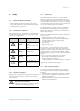
13 Technical data 13 Technical data 13.1 Controller VRC 470 Designation Unit VRC 470 Operating voltage Umax V 24 Current consumption mA < 50 Supply cable cross-section mm2 0.75…1.5 Protection type - IP 20 Protection class - III Max. permitted ambient temperature °C 50 Height mm 115 Width mm 147 Depth mm 50 Tab. 13.1 Technical specifications VRC 470 13.
Glossary 14 14 Glossary Auto_Off In the "Auto_Off mode" (Installer level), in Automatic mode the control functions outside active time periods can be specified separately for each heating circuit. There are three control modes (frost protection, ECO, set-back temp.) available for selection, which can be further adapted through the use of the room temperature control.
14 Glossary Heating flow temperature The boiler heats water which is then pumped through the heating installation. The temperature of this hot water as it leaves the boiler is referred to as the flow temperature. HK2 HK2 refers to heating circuit 2 in addition to the unitinternal heating circuit 1. It therefore refers to the first heating circuit in the heating installation. Hot water production The boiler heats the water in the domestic hot water cylinder to the selected target temperature.
Index Index A F Accessories............................................................................... 8 Activating the solar pump kick ......................................... 35 Advanced functions ............................................................. 32 Anti-Legionella function .......................................... 6, 33, 39 Article number ........................................................................ 4 Automatic summer time recognition................................
Index P T Parallel charging (domestic hot water cylinder and mixing circuit) ........................................................................ 34 Parameter ............................................................................ 9, 17 Pump Blocking Time ............................................................ 29 Target room temperature ........................................... 9, 17, 31 Target temperature for domestic hot water cylinder...................................................
Supplier Manufacturer 0020116690_00 GBIE 042011 – Subject to change *2702416_rev0*