
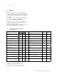
Technical data


Installation
12
Installation instructions VRC 470 0020116690_00
4
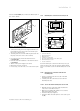
> Use the screws supplied to secure the wall mounting
base.
> Connect the eBUS cable to the terminals of the pin
header (¬Section5.3).
Installing the controller
> Carefully insert the controller in the wall mounting
base. Take care to ensure that the pin header (5) on
the wall mounting base fits in the controller connec-
tor provided.
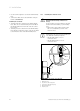
> Carefully press the controller into the wall mounting
base until the locking tabs on the controller are heard
to latch into the sides of the wall mounting base.
4.5 Installing the external sensor
b
Caution!
Risk of material damage if fitted incor-
rectly!
Incorrect fitting can cause damage to the unit
and the wall of the building, e.g. from damp-
ness.
> Observe the cable routing described and
the correct installation position of the
external sensor.
i
Installation is the same for both external sen-
sors, with the following exceptions:
– the VRC 693 requires a 2-core
connection cable
– the VRC 9535 requires a 3-core
connection cable
5
4
2
3
1
2
3
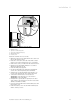
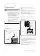
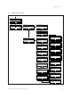
Fig. 4.3 Fitting the external sensor VRC 693
1 Mounting holes
2 Cap nut for cable entry point
3 Connection cable with drip loop
4 Wall mounting base
5 Housing cover