
Technical data


Operation
Installation instructions VRC 470 0020116690_00
21
7
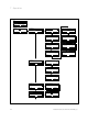
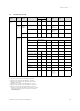
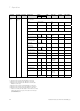
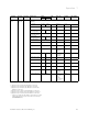
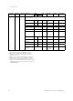
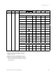
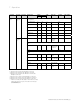
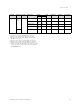
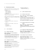
7.2 Installer level overview
Selection
level 1
Selection
level 2
Selection
level 3
Setting level Values Unit Step size,
select
Factory
reset
Own setting
min. max.
Installer
level
Enter code 000 999 – 1 000
Service
informa-
tion
Enter
contact
details
Installer 1 11 Figures A to Z,
0 to 9,
blank spaces
Phone 1 12 Num-
bers
0 to 9,
blank spaces,
hyphen
Service
date
Next service on Date
System
configura-
tion
System
Status Current value* –
Water pressure Current value bar
Domestic hot water Current value °C
Collector temp.
1)
Current value °C
Frost protect. delay 0 12 h 1 4
Pump Blocking Time Off, 5 60 min 1 15
Max. pre-heat 0 300 min 10 0
Max. pre-switch-off 0 120 min 10 0
OT constant heating Off, -25 10 °C 1 Off
Raising
temperature
2)
015K 0
Control modules List Software
version
Heating circuit
conf.
2)
Ht crt. 1,
Htcrt. 2,
Ht crt. 1 &
Ht crt. 2
Ht crt. 1
Tab. 7.1 Installer level overview
1) Appears only if solar module VR 68/2 is connected.
2) Appears only if mixing module VR 61/2 is connected.
3) Appears only if mixing module VR 61/2 or solar module
VR68/2 is connected.
4) Appears only if cylinder actoSTOR VIH RL is connected.
5) Appears only if remote control unit VR 81/2 is connected.
6) Appears only if no mixing module VR 61/2 is connected.
* If there is no fault, then the status is "OK". If there is a fault,
"Fault" appears here and you can read the error message
(¬Section10.2) here.