
Technical data

Operation
26
Installation instructions VRC 470 0020116690_00
7
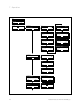
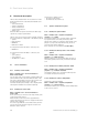
Selection
level 1
Selection
level 2
Selection
level 3
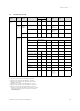
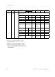
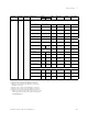
Setting level Values Unit Step size,
select
Factory
reset
Own setting
min. max.
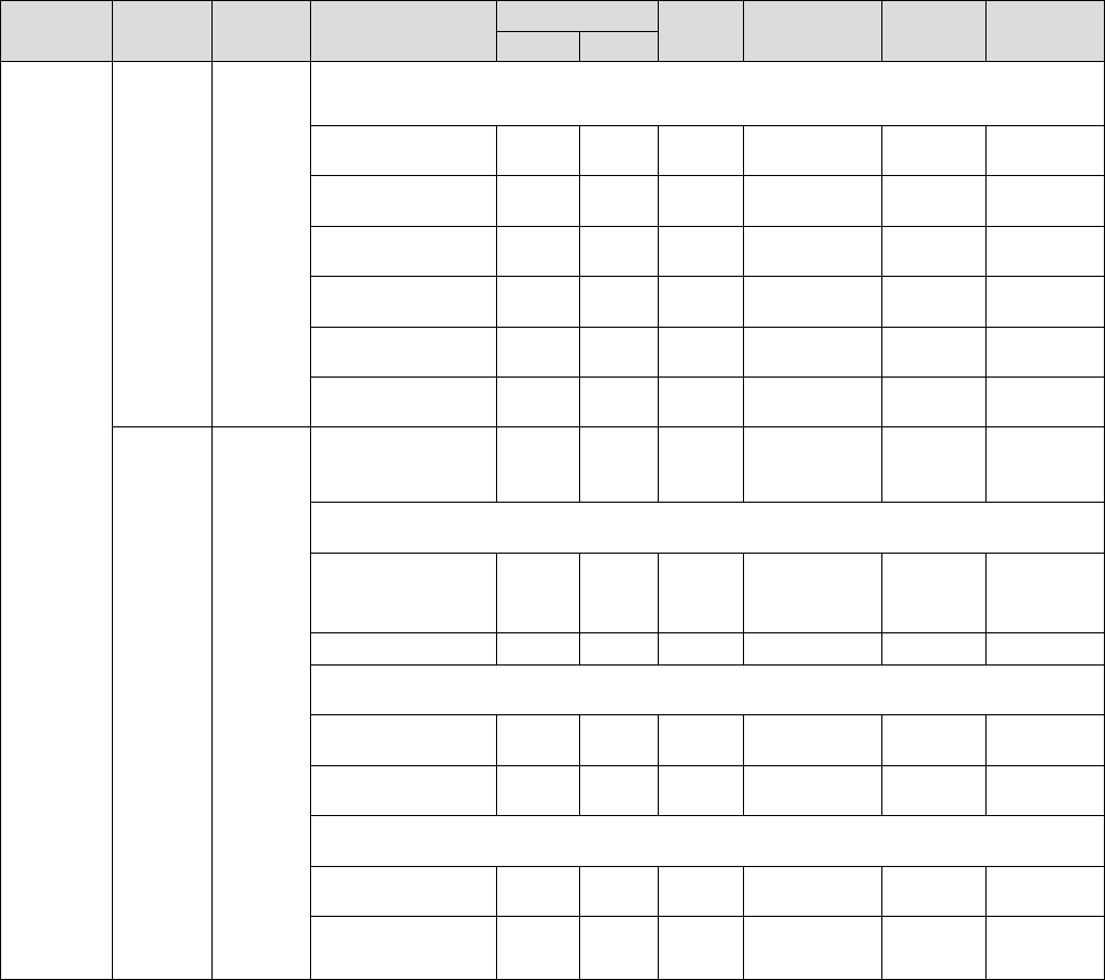
Installer
level
System
configura-
tion
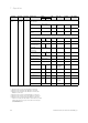
Solar cylinder 2
1)
Max. temperature 20 90 °C 1 65
On temp. diff. 2 25 K 1 7
Off temp. diff. 1 20 K 1 3
2nd Difference con-
trol
On temp. diff. 2 25 K 1 7
Off temp. diff. 1 20 K 1 3
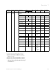
Sensor/
actuator
test
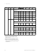
Select module – – – Connected
expansion
modules
VR 61
2)
Actuator – LP/ZP, HK1-P,
HK2 AUF, HK2
ZU, HK2-P
Sensor VF2 VF2
VR 68
1)
Actuator – – – MA, KOL1-P,
LEG-P
Sensor KOL1, SP1, SP2,
Yield, TD1, TD2
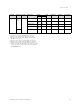
actoSTOR
4)
Actuator – – – ZP, P1, P2, AL
Sensor T1, T2, T3, T4,
Anode
1) Appears only if solar module VR 68/2 is connected.
2) Appears only if mixing module VR 61/2 is connected.
3) Appears only if mixing module VR 61/2 or solar module
VR68/2 is connected.
4) Appears only if cylinder actoSTOR VIH RL is connected.
5) Appears only if remote control unit VR 81/2 is connected.
6) Appears only if no mixing module VR 61/2 is connected.
* If there is no fault, then the status is "OK". If there is a fault,
"Fault" appears here and you can read the error message
(¬Section10.2) here.