INSTRUCTIONS FOR INSTALLATION AND SERVICING TURBOmax VUW 242/1 E TURBOmax VUW 282/1 E Wall hung room sealed fan assisted combination boilers HEATING, CONTROLS, HOT WATER.
Page 3 1. Introduction 2. 2.1 2.2 2.3 2.4 Boiler Specification Technical Data Dimensions Boiler connections Function diagram 3. 3.1 3.2 3.3 3.4 3.5 3.6 3.7 General Requirements 7 Related documents 7 Boiler location 7 Gas supply 8 Flue system 8 Air supply 10 Electricity supply 10 Guide to system requirements 10 4. 4.1 4.2 4.3 4.4 4.5 4.
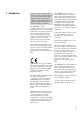
1. Introduction Note: This boiler must be installed and serviced by a competent person in accordance with the Gas Safety (Installation and Use) Regulations 1994. In the UK 'CORGI' Registered Installers undertake the work to a safe and satisfactory standard. The TURBOmax is a fully automatic, wall mounted, room sealed combination boiler for central heating and domestic hot water.
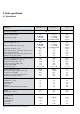
2. Boiler specification 2.1 Technical data TURBOmax VUW 242/1 E VUW 282/1 E units 29.3 (100,000) 9.6-24.0 (32,800-81,900) 34.2 (116,600) 11.2-28.0 (38,200-95,500) kW (Btu/h) kW (Btu/h) DHW flow rate @ 35 °C rise Mains water pressure required for max. flow rate Minimum water flow rate Mains water pressure required for min flow rate Maximum inlet water pressure 29.3 (100,000) 9.6-24.0 (32,800-81,900) 10 0.8 2.7 0.3 10 34.2 (116,600) 11.2-28.0 (38,200-95,500) 11.5 1.0 2.7 0.
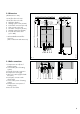
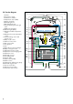
2.2 Dimensions (All dimensions in mm) 120 max. 995* 1a 120 max. 995 * 190 95.5 Air/flue duct to the rear Air/flue duct to the side Appliance bracket Heating system return (22 mm) Cold water connection (15 mm) Gas connection (15 mm) Hot water connection (15 mm) Heating system flow (22 mm) Pressure relief valve outlet (3/4 in BSP) 1a 1b 2 480 1021 * with standard horizontal flue accessory. (max. = 2965 mm with extensions) 880 1a 1b 2 3 4 5 6 7 8 35 50 fig. 1 2.
2.
3. General requirements 3.1 Related documents 3.2 Boiler location The installation of the boiler must be in accordance with the relevant requirements of Gas Safety (Installation and Use) Regulations 1994, Health and Safety Document No. 635 (The Electricity at Work Regulations 1989), BS7671 (IEE Wiring Regulations) and the byelaws of the local Water Undertaking.
3.3 Gas supply The gas supplier should ensure the availability of an adequate supply of gas. A gas meter may only be connected to the service pipe by the supplier of gas or their contractor. An existing meter should be checked to ensure that it is capable of passing the rate of gas supply required. Installation pipes should be fitted in accordance with BS 6891. Pipework from the meter to the boiler must be of an adequate size. Do not use pipes of a smaller size than the boiler gas connection (15 mm).
3.4.1 Flue Termination 1. The terminal must be positioned such that the combustion products can disperse freely at all times. 2. In certain weather conditions a plume of water vapour may be visible from the flue terminal. Positions where this could be a nuisance should be avoided. A G ,I F J F H E Table 1: Terminal position for fan-assisted flue (minimum distance - see fig. 5) A- Directly below an openable window or other opening (e.g.
3.5 Air supply 3.6 Electricity supply Detailed recommendations for air supply are given in BS 5440: Part 2. A 230 V~ 50Hz single phase electricity supply fused to 3 amps must be provided in accordance with the latest edition of BS7671 (I.E.E. Wiring Regulations) and any other local regulations that may apply. It is not necessary to have an air vent in the room or internal space in which the boiler is installed. 3.5.
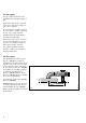
3.7.2 Filling and make up Heating circuit return Stop valve Double check valve assembly Hose unions Mains water supply Test valve Temporary Hose GW 400/1 The system should be filled with water via a separate filling point fitted at a convenient position on the heating circuit. Where local Water Authority Regulation allows, a temporary connection to the mains may be used (fig. 6). The connection must be removed when filling is completed.
If the nominal capacity of the built in expansion vessel is not sufficient for the heating system (for instance in case of modernisation of old open systems) an additional expansion vessel can be installed external to the boiler. It should be fitted in the return pipe as close as possible to the boiler in accordance with BS 5449: Part 1. Guidance on the sizing of an additional expansion vessel is given in Table 2. 3.7.6 Circulating pump The circulating pump is included in the boiler.
4. Boiler installation sequence 5mm 5mm 4.1 General 165mm The boiler should be mounted on a flat and vertical area of wall of sufficient area for the boiler plus the required minimum clearances for installation and servicing (fig. 10). These are shown on the installation template supplied with the boiler and are: 5 mm either side of the boiler 100 mm below the boiler* 165 mm on top of the boiler 500 mm in front of the boiler ** * 150 mm where optional preinstallation connecting group (Art. no.
4.2.1 Installation accessories Table 3 lists the standard and optional accessories which are available for the TURBOmax combination boilers. 4.2.2 Unpack the boiler (fig. 11) Open the boiler carton and remove: a. protective cardboard sheet b. top and bottom decorative panels c. polystyrene packaging Note: Care should be taken not to scratch the white surface of the boiler casing.
4.3.2 Using the boiler template (fig. 12) 4.3.2.1 Once a suitable location has been chosen, fix the paper installation template on the wall ensuring that the centerline of the template is vertical using a spirit level or plumb line. The template shows the positions of the fixing holes for the boiler hanging bracket (2) and the optional pre-installation connection group (3).
4.5.2 Fitting the boiler (fig. 13) Lift the boiler up to the wall so that it is slightly above the hanging bracket. Note: Lift the boiler from under the front edge of the side panels. Do not lift the boiler by the control box. Do not attempt to lift the boiler without the side panels or side casing fitted. Lower the boiler slowly onto the hanging bracket so that the cross member at the top rear of the boiler fully engages into the hanging bracket. 4.5.3 Pipework connections (fig.
4.5.3.4 Gas supply The boiler is supplied with a 20 x 15 mm gas service valve (10, fig. 14). Fit the 20 mm compression fitting to the boiler gas inlet (11, fig. 14) and tighten. Install a gas supply pipe not less than 15 mm diameter and connect to the gas service valve. (Ensure the gas supply pipework is adequately sized such that a 20 mbar - (8" w.g.) gas pressure is available at the boiler inlet at full flow rate). Tighten all union connections. 4 3 5 1 6 GW 823/1 2 fig. 17 4.
4.6.2 Vertical Flue Remove the two half rings (2, fig. 18) and, if necessary, fit the flue restrictor ring. (Note: It will be necessary to remove both half rings if the flue restrictor ring is to be fitted. The flue restrictor ring should be placed on top of flue outlet directly below the two half rings (see fig. 18A). One half ring should be replaced immediately). Fit the 63 mm diameter x 68 mm wide flue duct sleeve (2, fig. 22) over the flue gas duct of the air/flue duct assembly.
GW 603/1 2 fig. 25 4.7 Electrical installation 1 3 fig. 26 GW 614/1 4.7.1 General electrical requirements All electrical work shall be carried out by a competent person and shall comply with BS7671 (IEE Regulations). The boiler is supplied for connection to a 230V~ 50Hz supply fused at 3A rating. Connection to the mains supply should be made via a fused 3 pin plug to an unswitched, shuttered socket, both complying with the requirements of BS1363.
Connection details for programmable thermostats 2 3 4 4 → → 3 1 N L 3 N L 1 3 4 3 → ACL Drayton Lifestyle CT171, CT172, PT271, PT371 2 → 1 → L → N → → L ACL Drayton PT110, PT170 → N 3 4 2 3 4 OFF ON 2 4 → → 3 2 3 4 → Honeywell CM51, CM41 1 → Danfoss Randall TP2, TP3, TP4, TP5 A B → 4 Q1 Q2 → → 5 → 4 C → 3 3 → 3 Landis & Gyr REV 10 and 21 2 4 1 ACL Drayton Digistat 2 and 3 L 1 N C OFF ON fig.
4.8.3 Thermostatic radiator valves The boiler has a built-in automatic bypass valve making it ideal for use in systems with thermostatic radiator valves (no separate system bypass is required). For optimum fuel economy it is recommended that where TRVs are used they are used in conjunction with a programmable roomstat or separate timer and room thermostat to ensure complete boiler shutdown when the heating demand is satisfied.
5. Commissioning 5.1 Preliminary electrical checks Check the electrical installation by carrying out short circuit, earth continuity and resistance to earth tests and a check for correct polarity. 5.2 Gas supply 3 5.3 Water supply 1 Open all domestic hot water taps supplied by the boiler, turn on the mains water supply to the boiler and open the mains water isolating valve below the boiler (2, fig. 31). Water will now flow through the boiler to the hot taps.
5.4 Filling the heating system 2 1 fig. 32 GW 634/1 The boiler primary circuit and the heating system should be filled using a filling method as described in Section 3.7.2. Ensure that the boiler CH service valves (3, fig. 31) are open. Partially open the filling valve and allow water to enter the system. Starting with the lowest radiator, open the radiator air release until water (clear of bubbles) is emitted.
• • • • • • • • chamber (5, fig. 33) is correctly fitted. Ensure the cold water shut-off valve (4, fig. 34) is open by turning anti-clockwise. Open the gas service valve (2, fig. 34) Check that the CH service valves (1 and 5, fig. 34) are open. Check that all external heating controls are calling for heat. Switch on the electricity supply to the boiler. Set both the maximum hot water temperature control (4, fig. 33) and maximum radiator temperature control (3, fig. 33) to '9'.
• fig. 35 5.7 Gas inlet working pressure 1 2 Check the gas inlet working pressure by slackening the sealing screw and attaching a U gauge to the test point (3, fig. 36) on the inlet to the gas valve. Fire the boiler at full rate by opening a hot water tap. Check that the U gauge is reading 20 mbar. (If the pressure is not 20mbar this should be investigated before continuing with the commissioning procedure.
5.9 Adjusting the central heating output (range rating) • Stop turning the potentiometer when • • • • the burner pressure is at the correct setting for the output required (see table 5). Turn the boiler off. Remove U gauge. Tighten the sealing screw, (1, fig. 36) and test for soundness. Refit plastic plug in chamber sensing tube. After setting, refit cover screw (1, fig. 39) and re-secure control panel (1, fig. 38). 26 2 fig. 38 fig.
5.10 Functional Checks 5.10.1 Introduction The Vaillant TURBOmax is equipped with a set of diagnostic indicator lights to show the operational status of the boiler. A functional check of DHW and CH operation can be made using these indicator lights (fig. 41). 7 5.10.3 Functional check of central heating • Ensure that the power on indicator is illuminated. • Set the boiler central heating control to the 'Central Heating and Hot Water' position ( ). • Ensure external controls are calling for heat.
5.12 Final system flush ('hot') Allow the boiler and system to reach maximum temperature and check that the heating system is watertight. Turn the boiler off and rapidly drain both boiler and system while still hot. Refill the system and release all air as described in Section 5.4. Release water from the system until the system design pressure of 1.2 bar is attained. (The actual reading on the pressure gauge - (6, fig. 33) - should ideally be 0.
Set the maximum radiator temperature control (3, fig. 44) to the desired setting. The following settings may be used as a guide: Spring and Autumn Winter (normal) Winter (severe) 5–6 6–7 7–9 Note: if the setting is too low the radiators may not reach the desired temperature. Set the maximum hot water temperature control (4, fig. 44) to the desired setting. For normal circumstances the maximum hot water temperature should be set to 6.
6.2 Routine maintenance 4 3 5 1 6 GW 823/1 2 fig. 45 6.2.3 Remove combustion chamber front cover (5, fig. 44) Remove four screws (2, fig. 54) securing combustion chamber front cover Lift combustion chamber clear of top retaining lugs and pull forward. Remove combustion chamber cover by first bringing the left side forward to clear boiler casing. 6.2.4 Inspect main heat exchanger Remove five screws securing heat exchanger front panel (1 and 3, fig. 48) and remove by gently pulling down and forward.
1 3 GW 639/1 6.2.6. Check central heating expansion vessel Note : It is not necessary to carry out this check every year - a check every three years should be sufficient. Release the pressure from the boiler as described in section 7.1.2. Remove valve cap from expansion vessel charge point (2, fig. 49). Check that internal charge pressure of expansion vessel is between 0.7 - 0.9 Bar. If pressure is lower than this the vessel should be re-pressurised using an air pump. Refit valve cap (2, fig. 49).
IMPORTANT: Before starting any maintenance work: • Isolate the mains electricity supply • • • • by disconnecting the plug at the socket outlet (if there is an isolating switch only, remove the fuse from the switch). When removing any water carrying components ensure that the control box cover and terminal box cover are in position and water is kept away from all electrical components. Turn OFF the gas supply at the gas service valve fitted to the boiler.
7.1.5 Removal of combustion chamber cover (fig. 54). Remove front casing as in section • 7.1.3, • Remove four screws (2) securing combustion chamber front cover • Lift combustion chamber cover clear of top retaining lugs and pull forward • Remove combustion chamber cover by first bringing the left side forward to clear boiler casing.
7.2 Replacement of fan (fig. 55) • Isolate the boiler from the electrical • • • • • 4 GW 639/1-a • supply. Remove front casing as in section 7.1.3, and remove combustion chamber cover as in section 7.1.5. Disconnect the electrical connections from the fan. Remove the 2 fan securing screws (4) and remove fan. Reassemble in reverse order. Re-fit combustion chamber and front casing. Carry out electrical checks (see section 5.1). fig. 55 2 1 7.3 Replacement of air pressure switch (fig.
7.4 Replacement of burner fig. 57 • Isolate the boiler from the electrical • • • • • 5 4 2 3 1 6 GW 641/1 • supply. Remove front casing as in section 7.1.3. Remove combustion chamber cover as in section 7.1.5 Disconnect the ignition and flame sensing electrode leads (1, fig. 57). Remove two screws (2, fig 57) and pull burner forwards to remove. Reassemble in reverse order. Carry out electrical checks (see section 5.1) and check burner pressure (see section 5.8) and gas rate. 7.
7.6 Replacement of NTC temperature sensor 5 4 3 1 2 • Disconnect boiler from electricity • • • • • supply. Remove front casing as in section 7.1.3 and remove combustion chamber cover as in section 7.1.5 Pull off connecting wire to sensor. Unscrew NTC sensor. (4, fig 62) Reassemble in reverse order. Carry out electrical checks (see section 5.1). 6 fig. 59 GW 643/1 Note: The NTC temperature sensor is an extremely reliable component and as such is unlikely to fail.
7.7.1 Replacement of modulating regulator 7.8 Replacement of main heat exchanger • Isolate the boiler from the electrical • Turn off the boiler as in section • • Remove front casing as in section • • • • • • • • • • • • • • • 7.1.3 and remove combustion chamber cover as in section 7.1.5 Remove heat exchanger front panel as in section 7.1.7 Release CH water pressure and drain boiler as in section 7.1.2. Remove burner assembly as in section 7.4. Pull off wire from NTC (4, fig.
7.9.1. Boiler installed with air/flue duct to left/right hand side, or vertical flue installation (where 300mm vertical clearance exists above the boiler). • Remove front casing as in section 7.1.3 • Turn off the boiler as in section 7.1.1. • Release CH water pressure and drain boiler as in section 7.1.2. • Remove combustion chamber cover as in section 7.1.5 • Remove 2 screws (2, fig 63). • Remove screw (1, fig. 56) to release air pressure switch. • Slide expansion vessel upwards and out of boiler casing.
7.10 Replacement of transformer • Pull pump forward to remove. • Fit new '0' rings (supplied with • Isolate boiler from the electricity • • • • • • 7.11 Replacement of overheat thermostat • • • • • • • Isolate the boiler from the electricity supply. Remove front casing as in section 7.1.3. Lower front panel as in section 7.1.6. Pull wires off overheat thermostat (2, fig 66). Unscrew overheat thermostat to remove. Reassemble in reverse order. Carry out electrical checks (see section 5.1). fig.
7.15 Replacement of diverter valve • Turn off boiler as in section 7.1.1. • Remove front casing as in section • Turn off boiler as in section 7.1.1. • Remove front casing as in section 2 • • 1 • • 7.14 Replacement of automatic bypass • Turn off boiler as in section 7.1.1. • Remove front casing as in section • • • • • • • • • 7.1.3. Release CH water pressure and drain boiler as in section 7.1.2. Lower front control panel as in section 7.1.6. Remove spring clip (1, fig. 66).
2 5 4 1 fig. 72 7.16 Replacement of pressure and temperature gauge • • • • • • • • • Turn off boiler as in section 7.1.1. Remove front casing as in section 7.1.3. Release CH water pressure and drain boiler as in section 7.1.2. Lower front control panel as in section 7.1.6. Undo union (2, fig 71) on diverter valve to release pressure gauge tube. Remove temperature gauge phial from pocket on primary flow pipe. Press spring clips on side of gauge to remove from front panel. Replace in reverse order.
7.18 Replacement of DHW microswitch. • Isolate appliance from electricity • • • • • • supply. Remove front casing as in section 7.1.3. Lower front control panel as in section 7.1.6. Lift off microswitch retaining ’bow’ spring, Pull microswitch forward to remove from mounting bracket and disconnect wires. Reassemble in reverse order. Carry out electrical checks (see section 5.1). 1 7.19 Replacement of DHW heat exchanger • • • 7.1.3. Release CH water pressure and drain boiler as in section 7.1.2.
7.20 Removal of printed circuit boards (PCBs) 1 Before commencing work on PCB replacements carry out the following:Diagnose that the boards require changing using the fault finding guide (see section 8: Fault finding). 2 A • Turn off the boiler as in section • • • 7.20.1 Replacement of switch and control boards • Disconnect external wiring from boiler terminal strip. • Unplug ribbon cable from control board (2, fig. 75). • Unplug all leads from the both boards (1, fig. 75).
8.1 Introduction The TURBOmax has built in diagnostic indicator lights (fig. 77) to assist you with fault finding in the unlikely event of a boiler malfunction. The lights will illuminate in sequence, indicating the operational status of the boiler. Should a fault develop in the boiler the indicators may flash highlighting the possible fault e.g.
Repair external wiring fault. Note 1 For test purposes, disconnect external controls from terminals 3 - 4 and replace with a bridge between these terminals. If appliance then operates, the fault is with the external controls. Go to sheet B. Ensure boiler main on/off control is set to position ` `. Sheet A No No Go to sheet C. Yes Does green power `on` indicator glow now? Check and if necessary replace 2 A fuses situated below boiler terminal strip (spare fuse supplied with appliance).
Sheet B Boiler on/off control defective, replace electronic boards. No Is 230 V present across boiler terminals 3 and 5? Yes Replace electronic boards. No Check transformer (A, fig. 67) 230 V AC primary (black/ red) and approx. 17 V secondary (blue/brown) Does the indicator glow now? No Check, replace 1.25 A fuse next to the transformer plug (spare fuse provided with the appliance).
Sheet C External fault. Check whether all external controls are calling for heat, replace or repair as necessary (see also note 1, sheet A). No Is 230 V AC present across boiler terminals 4 and 5? No Does yellow central heating demand indicator ( ) glow? No Check central heating control switch is set to the position ( ). Yes If the central heating demand indicator ( ) still does not glow, replace electronic boards. Yes Go to sheet D.
Sheet D Yes Yes Replace electronic boards. No Is 230 V present at the pump plug connection (X10) on the electronic boards? No Turn boiler on/off control switch off, then on again. Check maximum radiator temperature control is set high enough (e. g. 9). Does the pump run now? No Does the yellow ignition indicator ( ) flash after 30s? No Does pump run? Yes Yes Check pump, replace as necessary.
Sheet E Yes No No Go to sheet C. No heat demand. No Does yellow central heating demand indicator ( ) glow? No Is 230 V present across fan terminals? No Does fan run now? Check pitot tube (in fan outlet) and air hoses are not obstructed and correctly aligned. Check or replace air pressure switch. Yes Does yellow fan operation indicator flash or glow? No Does yellow flame indicator ( ) flash? Does fan run? Yes Yes Yes Yes Switch main on/off control off and on again.
Sheet F Check continuity of microswitch. Replace if necessary. Check connection of ribbon plug to switch board. If burner still fails to light, replace electronic boards. Fill and vent system and boiler. Yes No Check for dirt or damage to the differential switch, supply tubes and diaphragm.
Sheet G Yes Yes No Yes Ignition transformer on electronic board defective, replace electronic boards. No Does sparking commence at burner now? Check all electrodes and leads for damage and correct connection. Replace if necessary. No Reset lockout (turn central heating control to position ( ) and release). Does sparking commence at burner? Check gas supply.
Sheet H Check air/flue gas system is correctly fitted and not obstructed. If lockout occurs replace electronic boards. Check/clean burner, ionization sensor and cable for defects, good contacts and correct position. Yes Replace modulating regulator of gas valve if burner still fails to increase to full rate. Check connections/operation of both solenoids, replace gas valve as necessary. Check potentiometer for partial load setting (see 5.9 C.H. range rating).
Sheet J Yes Yes Check/replace D.H.W. microswitch. Draw hot water at high rate. Yes Replace diverter section. No Check/clean diaphragm and venturi in the bottom part of the diverter valve/water section, replace as necessary. No Check cold water inlet pressure is sufficient. Check filter in cold water inlet is clean. Check cold water isolating valve (3, fig. 50) is fully opened (turn anticlockwise). Does lever move now? No Does actuating lever operate D.H.W.
9 Electrical diagrams 9.1 Functional Flow diagram: VUW 242/1 E, 282/1 E CONTROL BOX MAIN SWITCH F2A F2A L 2 N 1 MAIN TRANSFORMER MAIN SWITCHBOARD 230V 20V OVERHEAT THERMOSTAT POWER SUPPLY AIR PRESSURE SWITCH CONTROL BOARD plug in connector FANCONTROL b br FAN r IGNITION TRANSFORMER IGNITION ELECTRODES r plug in connector PUMP WATER-PUMP SELECTOR DHW MICRO SWITCH NOTE ALL UNCODED WIRES ARE BLACK NTC TEMPERATURE SENSOR brown red t transparent t GAS VALVE fig.
fig. 79 Ignition NTC sensor electrode Control box Flame sensing electrode Combustion chamber Fan Control board Main switchboard Water switch Ignition transformer Pressure differential switch Overheat thermostat Air pressure switch Main transformer Gas valve Pump 9.
9.3 Schematic appliance circuit diagram: VUW 242/1 E, 282/1 E b FAN br AIR PRESSURE SWITCH NTC TEMPERATURE SENSOR FLAME-SENSOR IGNITION-ELECTRODES t r r GAS VALVE PUMP PRESSURE DIFFERENTIAL SWITCH OVERHEAT THERMOSTAT DHW MICRO SWITCH 9 8 7 5 4 3 LN MAIN TRANSFORMER IGNITION TRANSFORMER green orange grey MAIN SWITCHBOARD CONTROL-BOARD CONTROL-BOX fig.
Key No. Description Part No.
09 10 fig. 88 GW 693/1 fig. 87 GW 684/1 GW 683/1 12 fig. 89 13 14 fig. 91 GW 682/1 fig. 90 GW 691/1 GW 686/1 15 fig. 92 18 17 N L 3 4 5 7 8 9 16 fig. 94 20 58 fig. 97 GW 681/2 fig. 96 GW 685/2 21 fig. 95 GW 692/1 fig.
11. Supplementary information for TURBOmax L.P.G. Appliances: The appliance delivered is designed for use with LPG. Please read the instructions for installation therefore as follows: Related documents to be supplemented by: Technical Data VUW 242/1 EB VUW 282/1 EB BS 5482: CP for domestic butane and propane gas burning installations Part 1: Installations in permanent dwellings Inlet pressure: Propane 37 mbar (14.6 in W.G.) Butane 28-30 mbar (11.0-11.8 in W.G.
Head Office Vaillant Ltd.