
Technical data
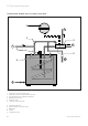


7.5 Discharge Pipework
The outlet connections of both the temperature and
pressure relief valve and expansion relief valve should
be connected in 15 mm copper tube to the tundish sup-
plied.
The tundish should be installed vertically, as close to the
VANTAGE as possible and within 500 mm of the tempe-
rature and pressure relief and expansion relief valve out-
lets. It must be positioned away from any electrical com-
ponents and installed in the same space as the
VANTAGE cylinder.
The discharge pipework must be installed using mini-
mum 22 mm copper pipework from the 1" inch BSP
female connection on the tundish to a safe and visible
discharge point. There must be a vertical section of pipe
at least 300 mm long, below the tundish before any
bends or elbows in the pipework. Increase the diameter
of the pipework if the total resistance of the discharge
pipework exceeds the figures shown in table 4.
Example
22 mm discharge pipe having 4 elbows and a length of
7 m from the tundish to the discharge point:
Resistance for 4 elbows
at 0.8 m each = 3.2 m
Resistance of discharge pipe = 7.0 m
Total Resistance = 10.2 m
The total resistance of the discharge pipework is
greater than the maximum allowed for 22 mm
pipework (9 m). Therefore calculate the next largest
size.
28 mm discharge pipe with 4 elbows and 7 m length
from tundish to discharge point.
Resistance for 4 elbows
at 1.0 m each = 4.0 m
Resistance of discharge pipe = 7.0 m
Total Resistance = 11.0 m
The total resistance of the dischargepipework is less
than the maximumallowed for 28 mm pipework (18 m)
therefore the discharge pipework size is acceptable.
Minimum size Maximum total resistance Resistance created
of discharge allowed expressed as a by each elbow
pipework length of straight pipe or bend
from Tundish (i. e. no elbows or bends)
22 mm up to 9 m 0.8 m
28 mm up to 18 mm 1.0 m
35 mm up to 27 mm 1.4 m
Installation requirements 7
Vaillant Vantage 120/150/200 19