
User`s guide


User's Guide ______________________________________________________________________
46 __________________________________________________________________ M210855EN-C
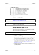
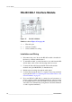
RS-422/485-1 Interface Module
0503-029
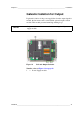
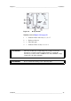
Figure 25 RS-485-1 Module
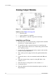
Installation and Wiring
1. Disconnect the power. In case the RS-485-module is installed in
the factory, continue with the item 4.
2. To attach the module, open the barometer cover and fasten the RS-
485 module to the bottom of the housing with four screws.
3. Connect the flat cable between the RS-485 module and the
motherboard's pins MODULE1 (Communications).
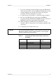
4. Pull the network wirings through the cable gland.
5. Connect the twisted pair wires (1 or 2 pairs) to the screw terminals
as presented in Table 4, Connecting the Twisted Pair Wires to the
Screw Terminals, on page 47.
6. If you use RS-485 (or RS-422) to connect just one barometer to a
master computer, enable the internal termination of the barometer
by switching switches 1 and 2 ON. Make sure that the master's end
of the line is also terminated (by using master's internal termination
or with a separate terminator).
Numbers refer to Figure 25 on page 46:
1 = Flat cable pins
2 = Selection switches
3 = Screw terminals for wiring