
Owner manual

Chapter 4 _________________________________________________________________ Operation
VAISALA ________________________________________________________________________ 83
User Port Connection
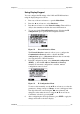
Use suitable serial cable between the user port RxD, GND and TxD
screw terminals and the PC serial port.
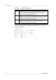
Table 13 Default Serial Communication Settings for the User
Port
Parameter
Value
Bauds
4800
Parity
Even
Data bits
7
Stop bits
1
Flow control
None
0506-033
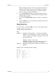
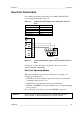
Figure 57 Connection Example between PC Serial Port and User
Port
Connections to pins 4,6,7 and 8 are required only if your software
requires hardware handshaking.
User Port Operating Modes
When the transmitter is powered up, it will behave according to its
configured operating mode:
- In STOP mode, the transmitter outputs the software version and the
command prompt (if echo is on).
- In RUN mode a measurement output starts immediately.
- In POLL or MODBUS mode, the transmitter does not output anything
after power-up.
For a description of the modes, see section SMODE on page 117.
NOTE
RS
-232 User Port cannot be used when a communication module
(LAN, WLAN, or RS
-422/485 interface) has been installed.
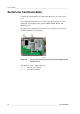
1 2 3 4 5
6 7 8 9
+
–
RxD
GND
TxD
Ch1+
Ch1–
Ch2+
Ch2–
ANALOG OUTPUTS USER PORT POWER
RS-232 10…36 V=
24 V~
IOIOI