
User`s guide
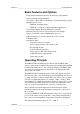
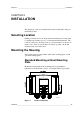
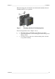

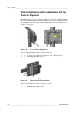
Table Of Contents
- DMT345/346 USER'S GUIDE
- TABLE OF CONTENTS
- GENERAL INFORMATION
- PRODUCT OVERVIEW
- INSTALLATION
- OPERATION
- Getting Started
- Display/Keypad
- MI70 Link Program for Data Handling
- Serial Line Communication
- LAN Communication
- Communicating with a Transmitter in POLL Mode
- General Settings
- Serial Output Settings
- Data Recording
- Analog Output Settings
- Operation of Relays
- Sensor Functions
- MODBUS
- MAINTENANCE
- CALIBRATION AND ADJUSTMENT
- TECHNICAL DATA
- EXAMPLE INSTALLATION OF DMT346
- CALCULATION FORMULAS
- MODBUS REFERENCE
Chapter 3 ________________________________________________________________ Installation
VAISALA ________________________________________________________________________ 29
Mounting with DIN Rail Installation Kit
DIN rail installation kit includes a wall mounting kit, 2 clip-fasteners and
2 screws M4 × 10 DIN 7985 (Vaisala order code: 215094).
1. Attach two spring holders to the plastic mounting plate by using the
screws provided in the installation kit.
2. Fasten the transmitter to the plastic mounting plate with 4 screws
(provided).
3. Press the transmitter onto the DIN rail so that the clip-fasteners
snap into the rail.
0604-013
Figure 9 Mounting with DIN Rail Installation Kit