
User guide


User's Guide _______________________________________________________________________
14 ___________________________________________________________________ M211501EN-C
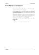
GMP231 Parts
1403-153
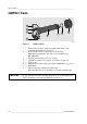
Figure 2 GMP231 Parts
1
=
Electronics housing. Contains the main component board,
including the digital pressure sensor.
2
=
Holes for M4 screws on both sides of the housing.
Maximum
screw depth 8 mm. Two screws included, type
BN 10649 M4.
3
=
Type label on housing cover (not shown).
4
=
8-pin M12 connector. For pinout, see Table 4 on page 24.
5
=
Probe body.
6
=
Measurement cuvette with optics and CARBOCAP
®
CO
2
sensor.
7
=
PTFE filter.
8
=
Silicone plug for sealing the lead-through.
Recommended accessory, suitable for ⌀ 44 mm lead-throughs.
CAUTION
Do not open the electronics housing; there are no user serviceable parts
inside. All wiring is done through the M12 connector (4).
3
2
4
1
5
6
7
8