
User guide


User's Guide _______________________________________________________________________
16 ___________________________________________________________________ M211501EN-C
1403-161
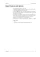
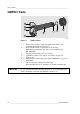
Figure 4 CO
2
Measurement Inside the Incubator
1
=
Chamber wall.
2
=
Chamber interior.
3
=
Light source.
4
=
Band pass filter.
5
=
Ambient air (400 ... 1000 ppm CO
2
).
6
=
Light absorbed by CO
2
in the incubator gas.
7
=
Thermopile detector.
8
=
Fabry-Perot interferometer.
9
=
Sapphire window. Separates the sensor’s active components
from the measured environment.
10
=
Gold-plated mirror.
1
2
3 4
5
6
7
8
9 10