
Instruction Manual


HMP230 SERIES
Appendix 3: RS 485/422 serial port module M210225en-A
110
3. NETWORK CONFIGURATION
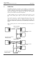
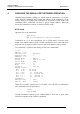
Single loop operation
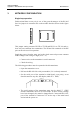
Bi-directional data on one pair is one of the great advantages of the RS 485
line. Set jumpers in connector X4 on the module board as shown in the figure
below.
X4
X4
X1 X2
This jumper setting connects RX HI to TX HI and RX LO to TX LO and se-
lects only one common line termination. The HI and LO terminals of the RX
pair can now be used for operation.
Supplying power from the same end to the whole network prevents common
mode voltages from rising too high (over 7 V).
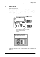
• Connect wires to the transmitter's serial connector.
• Check the wiring.
The following procedure must be repeated with all transmitters.
• Open the transmitter cover.
• Pull out the RS 485/422 serial port module, if it is already mounted.
• Set the serial port of the terminal to 4800 baud, even parity, seven
data bits and one stop bit, full duplex (4800 E 7 1 FDX).
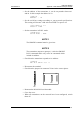
RX GND T
X
X17
• The serial settings of the transmitter must also be 4800 E 7 1 FDX
and the transmitter must be in STOP mode. If these factory settings
have been changed, they must be changed back. Connect the RS 232C
port of the terminal to connector X17 on the top of the main board
and switch the power on.