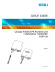
QUICK GUIDE Vaisala HUMICAP® Humidity and Temperature Transmitter HMT140 English M211484EN-A
PUBLISHED BY Vaisala Oyj P.O. Box 26 FI-00421 Helsinki Finland Phone (int.): Fax: +358 9 8949 1 +358 9 8949 2227 Visit our Internet pages at www.vaisala.com. © Vaisala 2012 No part of this manual may be reproduced in any form or by any means, electronic or mechanical (including photocopying), nor may its contents be communicated to a third party without prior written permission of the copyright holder. The contents are subject to change without prior notice.
__________________________________________________________________________ Table of Contents ENGLISH ........................................................................................................ 5 Product Overview ..................................................................... 5 Dimensions ............................................................................... 6 Duct Installation Kit.................................................................. 7 Wiring ........................
QUICK GUIDE ______________________________________________________________ This page intentionally left blank.
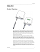
____________________________________________________________________ English ENGLISH Product Overview The Vaisala HUMICAP® Wireless Humidity and Temperature Transmitter HMT140 measures relative humidity and temperature using the connected probe and analog signals – RTD, Voltage, Current loops and Contacts. It outputs data via wireless transmitter and is powered with three 3.6 volt DC batteries and optional 9-30VDC connection and comes in 2 models, with or without the optional LCD display.
QUICK GUIDE ______________________________________________________________ Dimensions 116 37 145 124 120 72 Ø 12 Wall Assembly dimensions 78 M4 ;4 pc s 91 39 46 92 6 _____________________________________________________________ M211484EN-A
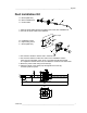
____________________________________________________________________ English Duct Installation Kit A A = Probe (HMP110) B = Duct installation kit C = Probe Cable B C 1. Pass the probe cable through the plastic pipe of the duct installation kit. 2. Connect the probe cable to the HMP110. Ø3,2x 4 pcs Ø24 42 D = Installation screw E = Pipe locking screw F = Probe (HMP110) F E D 3. Use a 24mm drill bit to make a hole in the duct wall. 4. Use a 3.
QUICK GUIDE ______________________________________________________________ Wiring Ir Sensor Status LED + P S 8 y 31 re 6 tt 23 a B N V / 6 P 3. la a s ai V Service Switch P S 8 1 y 3 re 6 tt 3 a 2 B N V /P 6 a .3 l a s ia V SERVICE + ON LCD Display Power Switch OFF CONFIG + Config Header Va is 3.
____________________________________________________________________ English 1) RTD Wiring Diagram Channel 1: RTD Channel 2: RTD VAISALA_________________________________________________________________ 9
QUICK GUIDE ______________________________________________________________ 4) Voltage Wiring Diagram Channel 2: DC Volatge 10 + VinDC V+ G V+ G V+ G V+ G Channel 1 Channel 2 Channel 1 Channel 2 Channel 1: DC Voltage + VinDC ____________________________________________________________ M211484EN-A
____________________________________________________________________ English Hardware Setup To set up the device initially: 1. Open the case by pulling out and up with your fingers while pressing the release tab located between the two glands with your thumb. (See the HMT140 components diagram in “Wiring” section for location of release tab). A slot screwdriver may be used to pry if you are unable to open the case by hand. 2. Ensure the power switch on the device is in the OFF position. 3. Install three 3.
QUICK GUIDE ______________________________________________________________ HMT140 Utility Software Setup Use the following procedure to quickly set up the HMT140: 1. 2. 3. 4. 5. 6. 7. 8. Turn on the HMT140 and wait 5 seconds. Plug the USB connector on the HMT140 Configuration Cable to the computer if it is not already connected. Open the HMT140 Utility from the start menu. Connect the end of the Configuration cable labelled “USB Wi-Fi Programmer” to the HMT140 “CONFIG” pin header.
____________________________________________________________________ English To reset the battery meter: 1. Turn off the HMT140. Make sure the configuration Cable is disconnected from the sensor. 2. Press and hold the service button. 3. Turn the HMT140 on while the service button is engaged. 4. Wait four seconds. 5. Release the service button. The battery meter has been reset. IR Sensor Use the following procedure to trigger a data packet transmission using the IR Sensor: 1.
QUICK GUIDE ______________________________________________________________ Technical Support The complete HMT140 User's Guide is available in English at www.vaisala.com/hmt140. For technical questions, contact the Vaisala technical support by e-mail at helpdesk@vaisala.com. Provide at least the following supporting information: - Name and model of the product in question. Serial number of the product. Name and location of the installation site.
____________________________________________________________________ English Technical Data Humicap Relative Humidity Measurement Specifications (With HMP110) Property Measurement range Accuracy (including non-linearity, hysteresis, and repeatability): at 0 ... +40 °C (+32 ... +104 °F) at -40 ... 0 °C and +40 ... +80 °C (-40 ... +32 °F and +104...+176 °F) Factory calibration uncertainty at 20 °C (+68 °F) Humidity sensor Stability Description / Value 0 ... 100 % RH ±1.7 %RH (0 ... 90 % RH) ±2.5 %RH (90 ..
QUICK GUIDE ______________________________________________________________ Analog Inputs Property 2 Channel Current input signals Description / Value 0-22 mA Resolution: 0.67 µA Accuracy: ±0.15 % F.S. at +25 °C Input Impedance: 62 Ohms 2 Channel Voltage input signals 0-5 V, 0-10 V Resolution 0.0034% F.S. ±0.15 % F.S. at +25 °C Input Impedance: 37K Ohms 2 Boolean Contacts Open /Close with magnetic reed relay cable connections Isolation One common per logger Overload Protection 40 mA max.
____________________________________________________________________ English Mechanics Specifications Property Operating Temperature Range Transmitter body, no display Transmitter body, with display Material Transmitter housing Display window Probe body Probe grid filter Housing classification Connections Screw terminals HMP110 Probe interface HMP110 Probe cable lengths RTD Temperature Sensor Sensor tip material Sensor tip length Sensor tip diameter Cable length Hermetic Door Switch Sensor Cable length Disp
QUICK GUIDE ______________________________________________________________ Property Description / Value Canadian requirements for unintentional radiators, IC ICES003:2004 European Union CE Marking requirements for process control, measurement, and laboratory equipment (EMC Directive 2004/108/EC):EN 61326-1:2006 for emissions and immunity EN 61326-2-3:2006 for emissions and immunity of transducers with signal conditioning EN 61000-3-2:2006+A1:2009 +A2:2009 for harmonics EN 61000-3-3:2008 for flicker Austral
_____________________________________________________________ Drilling template DRILLING TEMPLATE 78 91 39 46 M4 92 VAISALA_________________________________________________________________ 19
www.vaisala.