
User`s guide

User’s Guide ______________________________________________________________________
24 ___________________________________________________________________ M010056EN-J
0603-038
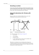
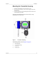
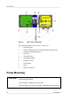
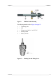
Figure 7 Parts of the Transmitter
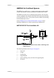
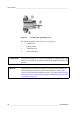
Probe Mounting
The following numbers refer to Figure 7 on page 24:
1 = Electronics unit
2 = Probe; including a part of the measurement electronics (for
example, calibration memory)
3 = Flat cable
4 = Transmitter base
5 = Grounding terminal
6 = Protective covers
7 = Cable glands
8 = Probe
9 = RS232C connector
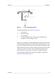
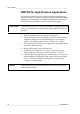
CAUTION
Do not unsolder and then resolder the probe cable from and to the printed
board during installation.
Do not shorten or lengthen the probe cable.
These procedures may alter the humidity calibration of the transmitter.