
Manual
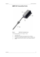

User's Guide _______________________________________________________________________
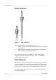
18 ___________________________________________________________________ M210474EN-C
Mounting the Transmitter/Removing the
Transmitter Unit
Select a place with stable conditions for mounting the transmitter. Do not
expose the transmitter to direct sunlight or rain. Always mount the
transmitter housing with the cable bushings pointing downwards.
NOTE
If the transmitter is mounted outdoors, cover it with a shelter (purchased by
customer). A rain shield designed for MMT310 is available as an optional
accessory. For information on ordering accessories, see section Spare Parts
and Accessories on page 69.
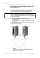
1. Mount the plate onto the wall with four/two screws
(Ø 4.5 mm/6.0 mm).
2. Place the transmitter onto the mounting plate and fasten it with two
Allen screws.
The transmitter module can be unfastened for calibration by releasing the
two Allen screws on the left side.
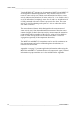
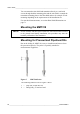
1403-181
Figure 3 Mounting with Mounting Plates
The following letters and numbers refer to Figure 3:
A
=
Mounting with larger mounting plate (mount from flanges)
B
=
Mounting with smaller mounting plate (remove the transmitter
and mount using the holes in mounting plate base)
1
=
Two Allen screws for fastening or removing the transmitter
module (Allen key provided)
2
=
Four screw holes (Ø 4.5 mm) for wall mounting (screws not
provided)
3
=
Two screw holes (Ø 6.0 mm) on the base of the plate for wall
mounting (screws not provided)