
Manual

User's Guide _______________________________________________________________________
28 ___________________________________________________________________ M210474EN-C
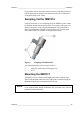
Connections
When the MMT310 leaves the factory, the measurement ranges, output
scaling and quantities have already been set according to the customer
order. The unit is calibrated at the factory and ready for use. The
transmitter is delivered with either a screw terminal connector or with a
detachable 5m cable with eight wires for serial port, analog outputs and
10 … 35 VDC power supply (requirements vary dependending on the
operating environment and output type). The wiring is described in this
section. For power supply requirements, see section Power Supply
Requirements on page 29.
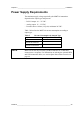
Cable Wiring
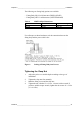
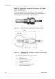
0507-044, 0507-045
Figure 12 8-Pin Connector (Left) and Screw Terminal
Connector (Right)
Pin
Wire
Serial Signal RS-232C
Analog Signal
1
White
Data out TX
-
2
Brown
-
Ch 1 - / Ch 2 -
3
Green
-
Ch 2 +
4
Yellow
-
Ch 1 +
5
Grey
Supply - / RS-232 GND
Supply -
6
Pink
Supply +
Supply +
7
Blue
Data in RX
-
8
Red
Not connected
Not connected