PTB 200 Digital Barometers 24th February 1993 SSD/Operating Manual 1 (28) PTB200-O0284-1.1 PTB 200 DIGITAL BAROMETERS 1 PRODUCT DESCRIPTION 2 2 INSTALLATION 3 2.1 2.2 2.3 2.4 2.5 2.6 2.7 3 4 5 6 7 8 9 3 4 5 Mounting Grounding Power connections Serial output mode connections Pulse output mode connections Pressure connections Multiple barometers on one RS 232C bus SERIAL COMMANDS 10 3.1 General 3.2 Configuration commands 3.3 Operating commands 10 11 19 ADJUSTMENT AND CALIBRATION 22 4.
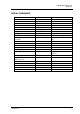
PTB200 Digital Barometer Appendix 1 SERIAL COMMANDS Function serial bus settings echo on/off output format pressure resolution units integration time settling time/response time sending mode address defining single output command sleep mode list of software settings Command SERI ECHO FORM FORM UNIT MTIM, FILT MTIM, FILT SMODE ADDR SCOM starting output stopping output output single reading R S SEND setting output interval control of a single barometer in POLL mode resetting error messages INTV OPEN ,CL
SSD/Operating Manual 1 PTB 200 Digital Barometers 24th February 1993 2 (28) PTB200-O0284-1.1 PRODUCT DESCRIPTION The PTB 200 A and PTB 201 A are fully compensated digital barometers designed to operate over a wide pressure and temperature range. The final factory adjustment and calibration of the PTB 200 A is done against a deadweight tester for best accuracy and pressure traceability.
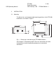
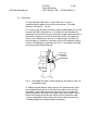
PTB 200 Digital Barometers 24th February 1993 SSD/Operating Manual 2 3 (28) PTB200-O0284-1.1 INSTALLATION 2.1 Mounting The dimensions and recommended mounting positions of the PTB 200 barometers are shown in Figure 1. 145 (5.71) 133 (5.24) Fig. 1 Dimensions and mounting of PTB 200 barometers See Chapter 2.2 Grounding and 2.6 Pressure connection for further information on electrical grounding and pressure connection alternatives. 139.5 (5.49) 120 (4.72) 104 (4.09) 27.5 (1.08) 65 (2.56) Ø 6.
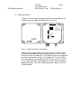
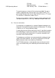
SSD/Operating Manual PTB 200 Digital Barometers 24th February 1993 4 (28) PTB200-O0284-1.1 2.2 Grounding A single electrical cable with a screen and five or six wires is recommended for power and serial bus connections. The cable diameter should be 5 ... 10 mm. The screen of the electrical cable must be grounded properly to achieve best possible EMC performance. First remove the bushing from the barometer housing and then push the cable through the bushing and its brass disks.
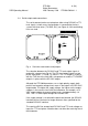
PTB 200 Digital Barometers 24th February 1993 SSD/Operating Manual 5 (28) PTB200-O0284-1.1 2.3 Power connections Two wires, one for supply voltage and another for supply ground, are needed to connect power to the barometer (see Fig. 3). POWER JUMPER ON normal use OFF external control using CTRL line + CTRL Fig.
SSD/Operating Manual PTB 200 Digital Barometers 24th February 1993 6 (28) PTB200-O0284-1.1 2.4 Serial output mode connections The serial communication can take place either using RS 232C or TTL level signals. In both cases the barometer is connected to the host system with three wires (TX, GND, RX) (see Figure 4). No handshaking lines are used. RS 232C T T L TTL INVERT T X GN D R X Fig.
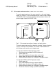
PTB 200 Digital Barometers 24th February 1993 SSD/Operating Manual 7 (28) PTB200-O0284-1.1 2.5 Pulse output mode connections (software version 1.05 or higher) The pulse output mode uses the same terminals as the serial output mode (see Figure 5). The transmitting terminal sends the pulse output (TX/PULSE) and the receiving terminal of the barometer receives the positive trigger signal (RX/PULSE TRIG).
SSD/Operating Manual PTB 200 Digital Barometers 24th February 1993 8 (28) PTB200-O0284-1.1 The pulse frequency is about 4.5 kHz at baud rate 9600. The pulse output is triggered using a positive pulse (e.g. 100 ms/5 VDC). The pulse output voltage levels can be either RS 232C levels or TTL levels. The selection is made with a jumper (Fig. 5). The pressure resolution is limited in the pulse output mode to 0.1 hPa. Each pulse represents 0.1 hPa, e.g. 10000 pulses equal 1000.0 hPa. 2.
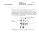
PTB 200 Digital Barometers 24th February 1993 SSD/Operating Manual 9 (28) PTB200-O0284-1.1 2.7 Multiple transmitters on one RS 232C bus It is possible to connect up to 99 PTB 200 barometers to one RS 232C bus by using a connector box with diodes for each barometer transmission line and one common barometer receiving line and ground line (see Figure 6). Each barometer must be initialized to POLL mode with a specific address (1...99) (see ADDR, SMODE POLL, OPEN and CLOSE commands).
PTB 200 Digital Barometers 24th February 1993 SSD/Operating Manual 3 10 (28) PTB200-O0284-1.1 SERIAL COMMANDS 3.1 General When delivered from factory the barometers are in serial full duplex RS 232C mode. No handshaking lines are in use. All commands are echoed.
PTB 200 Digital Barometers 24th February 1993 SSD/Operating Manual 11 (28) PTB200-O0284-1.1 The PTB 200 barometers have three sending modes: STOP, RUN and POLL modes. In STOP mode (factory setting) after power-up the barometer outputs its type code and software version number and then waits for further commands. In RUN mode pressure output starts automatically from power-up. POLL mode is meant mainly for adjustment and calibration where several barometers are connected to one RS 232C bus.
PTB 200 Digital Barometers 24th February 1993 SSD/Operating Manual Examples: >SERI 1200 E 7 12 (28) PTB200-O0284-1.1 1 >SERI 9600 E 7 9600 E 7 1 >RESET 1 >SERI 1200 1200 E 7 1 >RESET Always give the RESET command after the SERI command to invoke the new serial bus settings. The following bus settings do not work with the barometer’s Intel 8051 microprocessor and are modified by the barometer: N 7 1 ⇒ N 7 2 E 8 2 ⇒ E 8 1 O 8 2 ⇒ O 8 1 Note: N 7 2 works on software version 1.
PTB 200 Digital Barometers 24th February 1993 SSD/Operating Manual 13 (28) PTB200-O0284-1.1 The basic definition consists of the current and new format: >FORM (current output format appears here) ? (type new format here) The output format consists of the pressure reading area, pressure unit area, carriage return and line feed, e.g.: "\PPPP.PP\ \uuuu\\r\n" where \PPPP.
PTB 200 Digital Barometers 24th February 1993 SSD/Operating Manual UNIT 14 (28) PTB200-O0284-1.1 Setting the pressure unit UNIT x where x hPa*, kPa, mbar, inHg, mmHg, torr, psia (* factory setting). Command UNIT is used to select the pressure unit. Type the selected pressure unit as given above.
SSD/Operating Manual FILT PTB 200 Digital Barometers 24th February 1993 15 (28) PTB200-O0284-1.1 Setting the filter parameters FILT xxx yyyy where xxx ON or OFF yyyy FAST or SLOW The FILT command is used to set additional numerical filtering modes. FAST mode introduces a multiplication factor of 4 to the integration time set with the MTIM command. In addition a special algorithm that takes the derivative of the pressure change into account is used.
PTB 200 Digital Barometers 24th February 1993 SSD/Operating Manual SMODE 16 (28) PTB200-O0284-1.1 Setting the sending mode SMODE xxxx SMODE aa STOP STOP and RUN modes only POLL mode only where xxxx STOP, RUN or POLL aa the address (1...99) of the barometer in the POLL mode SMODE command sets or inspects the sending mode of the barometer. The factory setting is the STOP mode.
PTB 200 Digital Barometers 24th February 1993 SSD/Operating Manual ADDR 17 (28) PTB200-O0284-1.1 Setting the barometer address (for POLL mode only) ADDR ADDR is used to set or inspect an address (1...99) of a barometer for the POLL mode. Example of setting the address 7: >ADDR Address : 0 ? 7 A new address replaces the previous address.
PTB 200 Digital Barometers 24th February 1993 SSD/Operating Manual SLEEP 18 (28) PTB200-O0284-1.1 Setting and resetting the sleep mode SLEEP ON SLEEP OFF The SLEEP command is used to set and reset the software controlled sleep mode which cuts down the power consumption by over 60 %. In the sleep mode the current consumption is below 10 mA when no output is required and about 25 mA during output. By activating the sleep mode the barometer automatically falls asleep when no output is required.
PTB 200 Digital Barometers 24th February 1993 SSD/Operating Manual 19 (28) PTB200-O0284-1.1 3.3 Operating commands R Starting the measurement output R Command R starts the measurement output. The command is used to start output in the STOP and RUN modes (see SMODE command) and in interval output mode (see INTV command). S Stopping the measurement output S Command S ends the RUN mode.
PTB 200 Digital Barometers 24th February 1993 SSD/Operating Manual 20 (28) PTB200-O0284-1.1 Example of outputting the current settings: >INTV Output intrv. : 0 s Example of setting an output interval and starting outputting: >INTV 1 min Output intrv. : 1 min >R Example of cancelling the interval output mode: >INTV 0 s Output intrv. : 0 s OPEN CLOSE Setting a barometer to STOP mode (POLL mode only, software version 1.04 or higher) OPEN aa CLOSE aa where aa the address (1 ...
PTB 200 Digital Barometers 24th February 1993 SSD/Operating Manual RESET 21 (28) PTB200-O0284-1.1 Resetting the barometer RESET resets the barometer. All software settings remain in the memory after reset or any power failure. After changing the serial bus settings RESET must always be given to invoke them. ERRS Error message output ERRS ERRS command is used to print the error messages if any problems occur.
PTB 200 Digital Barometers 24th February 1993 SSD/Operating Manual 4 22 (28) PTB200-O0284-1.1 ADJUSTMENT AND CALIBRATION The PTB 200 barometers can be adjusted and calibrated against local primary standards that have high accuracy and stability as well as known traceability to international standards. The PTB 200 barometers are recommended to be adjusted or calibrated once a year when used in automatic weather station applications.
PTB 200 Digital Barometers 24th February 1993 SSD/Operating Manual 23 (28) PTB200-O0284-1.1 The following pressure adjustments are possible: • offset adjustment • offset/gain adjustment • multipoint adjustment at up to eight pressure levels. Offset and offset/gain adjustments are made with the barometer connected to a reference pressure (see LP command). With the LP command the pressure value of the primary standard is given to the barometer as a reference pressure and no separate corrections are needed.
PTB 200 Digital Barometers 24th February 1993 SSD/Operating Manual 24 (28) PTB200-O0284-1.1 Example of an offset and gain adjustment: >LP Ref1 ? (set first pressure level and enter value here) P : (the current non-corrected value appears here) Ref2 ? (set second pressure level and enter value here) P : (the current non-corrected value appears here) Use ESC to abort without executing a command. Return the MEMORY jumper to the EEPROM write disable position. 4.
SSD/Operating Manual PTB 200 Digital Barometers 24th February 1993 25 (28) PTB200-O0284-1.1 First precalibrate the barometer at up to eight pressure levels. Then calculate the corrections (reference value minus PTB 200 barometer indication) at each pressure level and enter the corrections using the MPCI commands. >MPCI 1. PTB reading correction 2. PTB reading correction ... 7. PTB reading correction 8. PTB reading ?499.64 ?0.024 ?599.79 ?0.013 ?1100.33 ?0.
PTB 200 Digital Barometers 24th February 1993 SSD/Operating Manual 5 26 (28) PTB200-O0284-1.1 TECHNICAL DATA OPERATING RANGE Pressure range Operating temperature range Storage temperature range Humidity range 600 ... 1100 hPa -40 °C ... +60 °C -60 °C ... +60 °C non-condensing Note: 1 hPa = 1 mbar (see note below). ACCURACY PTB 200 A PTB 201 A Linearity * ±0.05 hPa 1) ±0.10 hPa 2) ±0.03 hPa ±0.03 hPa ±0.10 hPa ±0.12 hPa 1) ±0.15 hPa 2) ±0.15 hPa ±0.1 hPa ±0.20 hPa ±0.1 hPa / a ±0.1 hPa ±0.
SSD/Operating Manual PTB 200 Digital Barometers 24th February 1993 27 (28) PTB200-O0284-1.
PTB 200 Digital Barometers 24th February 1993 SSD/Operating Manual 28 (28) PTB200-O0284-1.1 Dimensions in mm (inches) 145 (5.71) 133 (5.24) 139.5 (5.49) 120 (4.72) 104 (4.09) Ø 6.5 (0.26) 27.5 (1.08) 65 (2.56) 120 (4.
PTB200 Digital Barometer Appendix 1 SERIAL COMMANDS Function serial bus settings echo on/off output format pressure resolution units integration time settling time/response time sending mode address defining single output command sleep mode list of software settings Command SERI ECHO FORM FORM UNIT MTIM, FILT MTIM, FILT SMODE ADDR SCOM starting output stopping output output single reading R S SEND setting output interval control of a single barometer in POLL mode resetting error messages INTV OPEN ,CL