USER'S GUIDE Outdoor Mounting Kit PTU200MIK1 M210226EN-A
PUBLISHED BY Vaisala Oyj P.O. Box 26 FIN-00421 Helsinki Finland Phone (int.): +358 9 8949 1 Fax: +358 9 8949 2227 Visit our Internet pages at http://www.vaisala.com/ © Vaisala 2006 No part of this manual may be reproduced in any form or by any means, electronic or mechanical (including photocopying), nor may its contents be communicated to a third party without prior written permission of the copyright holder. The contents are subject to change without prior notice.
_________________________________________________________________________________ Table of contents CHAPTER 1 GENERAL INFORMATION ............................................................................2 Safety .........................................................................................2 Warranty ....................................................................................2 CHAPTER 2 PRODUCT DESCRIPTION.............................................................................
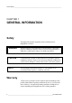
USER'S GUIDE_______________________________________________________________________ CHAPTER 1 GENERAL INFORMATION Safety Throughout the manual, important safety considerations are highlighted as follows: WARNING Warning denotes a serious hazard. It calls attention to a procedure, practice, condition or the like, which, if not correctly performed or adhered to, could result in injury to or death of personnel. CAUTION Caution denotes a hazard.
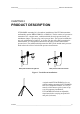
CHAPTER 2_______________________________________________________ PRODUCT DESCRIPTION CHAPTER 2 PRODUCT DESCRIPTION PTU200MIK1 mounting kit is for outdoor installation of the PTU200 transmitter and humidity probes HMP45/HMP233 or HMP 243. The kit consists of a protective transmitter box, a support arms, a radiation shield, the static pressure head, pole attachment clamps, a pressure pipe, and a pressure hose. The kit can be attached to any pole with diameter of either 2" or 60 mm.
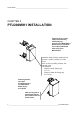
USER'S GUIDE_______________________________________________________________________ CHAPTER 3 PTU200MIK1 INSTALLATION Plastic bag (2 pcs.) include: Clamp for pole mounting Plastic fitting ring Hex bolt (2 pcs.) M8x40 DIN 931 Washer (2 pcs.) A 8.4 DIN 125 Hex nut (2 pcs.) M8 DIN 934 Allen screw (2 pcs.) M6x12 DIN 912 Attach the clamp with the machined side up to the T-profile with the two Allen screws. There are three possible positions: left, centered, right.
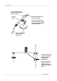
CHAPTER 3___________________________________________________ PTU200MIK1 INSTALLATION Installation when static pressure head is on the right side Installation plate 1.Mount the support arm on the upper clamp. Use the plate, two hex bolts and washers for the attachement as shown in figure. Radiation shield 2.Fasten the installation plate onto the support arm. 3.Mount the radiation shield the holes of the installation plate.
USER'S GUIDE_______________________________________________________________________ 7.Attach the pressure hose end to the threaded nipple of the pressure head. Threaded nipple. 8.Push the installation plate into the support arm. 9.Fasten the static pressure head to the end of the support arm (and installation plate) by using the two screws. 6.Thread the pressure hose through the support arm. 10. Connect the free end of the pressure hose to the hose coupling on backside of the transmitter box.
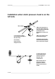
CHAPTER 3___________________________________________________ PTU200MIK1 INSTALLATION Installation when static pressure head is on the left side Boom adapter 3.Mount the support arm on the upper clamp. Fasten it by using the plate, two hex bolts and washers for the attachement as shown in the figure. 1. Insert the boom adapter into on support arm. Fasten it with two screws. 2 Join the two support arms by using two screws. 4.Mount the radiation shield as instructed on page 5. 5.
USER'S GUIDE_______________________________________________________________________ Connections in the transmitter box 1.Mount the PTU200 transmitter on the back plate of the transmitter box and attach it with the four Allen screws. 2.Thread the cables through the holes of the box and the gasket body. Allen key for opening the transmitter 3.Thread the cables through the hole in the bottom of the box. (The diameter of the bottom hole is 35 mm) 4.
CHAPTER 3___________________________________________________ PTU200MIK1 INSTALLATION Probe installations HMP45 series 1. Push the HMP45 probe through the plastic nut to the radiation shield as deep as it goes. 2. Pull back about 10 mm. 3. Finally, tighten the plastic nut. HMP233 series 1. Attach the HMP233 probe to the support with an upper cable tie. 2. Press the probe cable into the groove of the support. 3. Fasten the lower cable tie. 4.
USER'S GUIDE_______________________________________________________________________ HMP243 series 1. Attach the HMP243 probe to the support with an upper cable tie. 2. Press the probe cable into the groove of the support. 3. Fasten the lower cable tie. 4. Push the probe through the plastic nut into the radiation shield as deep as it goes. 5. Finally, tighten the plastic nut.
CHAPTER 4_________________________________________________PTU200TRIPOD INSTALLATION CHAPTER 4 PTU200TRIPOD INSTALLATION Place the pole onto the tripod stand and fasten it with the attachment screw. The handle of the screw is under the center of the stand. The legs of the stand are adjustable. To release the leg, lift the grip upwards. Adjust the leg to desired length and lock it by pressing the grip downwards. Open Locked Use the clamps without the fitting rings to attach the PTU200MIK to the pole.
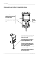
USER'S GUIDE_______________________________________________________________________ CHAPTER 5 DIMENSIONS in mm (in inches) 371 14.6024 353 13.8855 232 9.1142 Static pressure head on the left side 1136 44.7244 146 5.748 60 2. 36 51 ø 2 420 16.5354 22 ø 154 6.0447 ø 200 7.874 564 22.
CHAPTER 5__________________________________________________ DIMENSIONS IN MM (IN INCHES) 371 14.6024 353 13.8855 232 9.1142 Static pressure head on the right side 1134 44.626 51 ø 2. 36 22 ø 200 7.874 154 6.0447 60 534 21.0039 2 420 16.5354 ø 146 5.
www.vaisala.