
User Manual

2
VAL-MATIC'S 3"-24" SERIES 2000 BUTTERFLY VALVE
OPERATION, MAINTENANCE AND INSTALLATION
INTRODUCTION
The Series 2000 Butterfly Valve has been designed
to give years of trouble-free operation. This manual
will provide you with the information to properly
install and maintain the valve to ensure a long
service life. The valve is a resilient seated, quarter-
turn valve capable of handling air, water, or other
clean fluids. For fluids with suspended solids, a
Model 5800R Eccentric Plug Valve should be used.
The Size, Cold Working Pressure (CWP), and Model
No. are stamped on the nameplate for reference.
The "Cold Working Pressure" is the non-shock
pressure rating of the valve at 150
o
F. The valve is
not intended as a block valve for line testing above
the valve rating. The valve is intended for flow
toward the seat end of the valve. The typical flow
direction and “Seat End” are marked on the
nameplate. This allows seat adjustment while the
valve is holding system pressure.
RECEIVING AND STORAGE
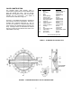
Inspect valves upon receipt for damage in shipment.
Unload all valves carefully to the ground without
dropping. Do not lift valves with slings or chains
around the actuator or through the seat area. Extra
care must be taken when handling electric motor
and cylinder actuated valves.
Valves should remain crated, clean and dry until
installed to prevent weather related damage. For
long term storage greater than six months, indoor
storage is recommended. The valve flange covers
must remain in place, the valve must remain slightly
open (3-5 degrees), and the rubber surfaces of the
disc should be coated with a thin film of FDA
approved grease such as Dow Corning # 7. Do not
expose the resilient seat to sunlight or ozone for any
extended period. Electric actuators must be
powered if stored outdoors or in cool areas so that
the internal heaters will prevent condensation in the
control unit.
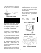
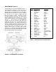
DESCRIPTION OF OPERATION
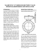
As shown in Figure 1, the valve consists of a body, a
disc, and a shaft that rotates in body bearings. The
resilient seat provides drop-tight shutoff.
FIGURE 1. BUTTERFLY VALVE WITH ACTUATOR
The disc is rigidly attached to the shaft with taper
pins. The actuator rotates the valve shaft and disc
through 90 degrees of operation. The disc can
rotate through the seat, but is factory set to stop in
the center of the seat to provide tight shut off.
Additional torque on the actuator when against the
closed stop of the actuator will not provide tighter
shut off. The valve seat is easily adjustable or
replaceable should wear or damage occur over time.
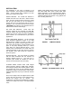
The valve can be operated with a hand lever or gear
actuator. The gear actuator as shown in Figure 1
requires multi-turn input on a 2" square nut,
handwheel, or chainwheel. The valve can also be
automated with power actuators such as an electric
motor or hydraulic cylinder.