
User Manual

6
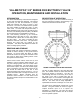
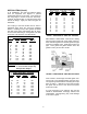
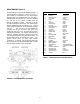
LEVER OPERATED VALVES: 8" and smaller
valves may be equipped with a top-mounted lever
for direct quarter-turn operation. To open the valve,
slowly rotate the lever 90° in the counter-clockwise
CCW direction.
FIGURE 6. LEVER ACTUATOR
VALVE
SIZE
PRESSURE
(PSI)
MODEL
NUMBER
L
(INCHES)
3”-4" 150 4BL 12
6" 150 6BL 12
8" 75 6BL 12
10" 75 10BL 18
12" 75 10BL 18
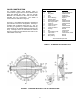
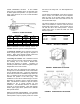
GEAR OPERATED VALVES: Butterfly Valves are
available with a two types of manual gear actuator.
A worm-gear actuator has a multi-turn worm that
drives a large sector gear through 90 degrees of
rotation. Worm gears provide uniform motion and
torque multiplication throughout the stroke.
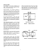
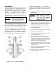
A traveling nut actuator has a threaded rod that
drives a nut from one end of the housing to another.
The traveling nut in turn drives a slotted lever
through 90 degrees of rotation. Traveling nut
actuators provide slower rotation and greater torque
multiplication at the ends of travel.
Both gear types are self-locking and multiply the
turning force on the handwheel or nut so that valves
can be operated with ease. A clamp-on chainwheel
kit can also be used for installations high above the
floor. An indicator on the top of the actuator housing
indicates the position of the valve plug. The
handwheel or nut must be rotated through 7-50 turns
(depending on model) to open or close the butterfly
valve. The direction of rotation to open the valve is
indicated on the 2" square actuator nut and
handwheel. The standard direction of rotation is
open left or counter-clockwise. Nuts with opposite
rotation (open right) will be painted red to indicate
their special rotation.
GEAR ACTUATOR ADJUSTMENT: The standard
gear actuator is provided with factory-set open and
closed position stops to properly center the closed
disc seal in the body seat. No field adjustment is
necessary.
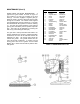
VALVE SEAT ADJUSTMENT: If the valve is found to
leak in service, the rubber seat can be adjusted.
With the valve in the closed position, tighten the
three seat bolts in the area of the leak 1/4 turn at a
time until the leak stops.
The factory settings for the seat bolts are given in
Table 3 for reference in case the valve can not be
tested while under pressure. These torques are for
use with the disc in the closed position. Torques
greater than 150% of these will make the valve
difficult to operate.
TABLE 3. SEAT BOLT TORQUES
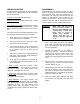
FIGURE 7. WORM GEAR ACTUATOR
FIGURE 8. TRAVELING NUT ACTUATOR
SIZES CLASS 150B CLASS 250B
3"-6" 6 ft-lbs 8 ft-lbs
8"-12" 8 ft-lbs 10 ft-lbs
14"-18" 12 ft-lbs 15 ft-lbs
20"-24" 15 ft-lbs 18 ft-lbs