
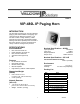
Specifications


2 947630
CAUTION: To reduce the risk of electric shock,
Do not remove cover.
No user serviceable parts inside.
Refer servicing to qualified service personnel.
CAUTION
RISK OF ELECTRIC SHOCK
DO NOT OPEN
This symbol indicates that dangerous
voltage constituting a risk of electric
shock is present within this unit.
This symbol indicates that there are
important operating and maintenance
instructions in the literature accompanying
this unit.
INSTALLATION
FCC Information
This equipment has been tested and found to
comply with the limits for a Class A digital
device, pursuant to Part 15 of the FCC Rules.
These limits are designed to provide reasonable
protection against harmful interference when
the equipment is operated in a commercial
environment. This equipment generates, uses
and can radiate radio frequency energy and if
not installed and used in accordance with the
instruction manual, may cause harmful
interference to radio communications.
Operation of this equipment in a residential area
may cause harmful interference in which case
the user will be required to correct the
interference at his own expense.
Precautionary Designations
Mounting (VIP-LLE)
The VIP-LLE Network Extender is designed for wall
or shelf mounting and must be within 300 feet of the
network switch.
Shelf: Provided with the VIP-LLE Network Extender
are four rubber stick on feet. Peel these feet off
their carrier backing and place at the four corners of
the bottom of the unit.
Wall: Using the brackets and wood screws
provided, secure the VIP-LLE Network Extender
to the wall.
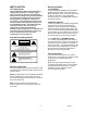
Mounting (HORN)
FLUSH MOUNT
Using the template packaged with the speaker,
draw the speaker outline on the wall to be cut.
Make appropriate wiring connections and test the
speaker for operation. Using appropriate
mounting screws (not furnished) drill and mount
the flange as shown.
UNIVERSAL BRACKET
Loosen or separate the universal bracket leaves
by loosening or removing the handle and
hardware. Using the back leaf as a template,
mark the wall through the mounting holes, drill
and mount to the wall using appropriate screws
(not furnished) or mount directly to a junction box.
Mount the T-bracket to the back of the horn as
shown using the (2) ½ inch screws provided.
“C” CLAMP FOR “I” BEAM MOUNTING
A “C” clamp is provided with the horn to allow
mounting to a beam. Place the bolt through the
hole in the bottom of the base to secure the “C”
clamp to the beam. It is suggested that the horn
be mounted to the underside of the “I” beam to
provide maximum positioning adjustments.
Mount (2) ½ inch screws provided.
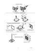
Interconnections
The only method of powering a VIP-480L IP
Paging Horn is via a power over Ethernet switch
or power injector meeting the 802.3af
specification.
Make all required signal connections before
connecting to Ethernet switch or power injector
meeting the 802.3af specification. Power is
supplied to the horn assembly via the
VIP-LLE Network Extender.