
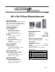
Specifications

4 947632
ALCOMV
VIP-172L
DOOR PLATE
AUX
NETWORK
STATUS
LINK
ACT
FRONT SIDE
R OO2
N/O
N/C
COM
VIP-172L
DOOR PLATE
VIP-172L
NETWORK
INTERFACE
900' MAXIMUM DISTANCE
STRIKE PLATE
CAT 3/5/6 UTP
POWER SUPPLY
NOTE: THE # DIGIT
ELECTRIC
ACTIVATES THE
RELAY.
STRIKE PLATE
SOLENOID
(802.3af Compatible PoE)
Network Port
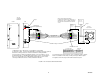
1. (Optional) If a door strike/release is to be utilized, connect wiring
to operate door strike. Connect to Normally Open or Normally Closed (as required)
and Common. Relay contacts are rated for a maximum of 1Amp at 24VDC.
2. Connect the Door Plate to the Network Interface. If the Door Plate is close to
Step 1
Step 2
3. Connect RJ45 connector from network. Power over Ethernet (PoE) is required;
if PoE is not available from the switch, an inline power injector will be required.
4. Program the VIP-172L using the VIP-102B IP Solutions Setup Tool.
Step 3
the Network Interface, a standard Patch Cable may be used to connect between
VM-186 COLOR CODES
ORANGE & WHITE / ORANGE
GREEN & WHITE / GREEN
BLUE & WHITE / BLUE
BROWN & WHITE / BROWN
WHITE/BLUE
BLUE
WHITE/ORANGE
ORANGE
WHITE/GREEN
GREEN
WHITE/BROWN
BROWN
Patch Cable
WHITE/BLUE
BLUE
WHITE/BROWN
WHITE/ORANGE
ORANGE
WHITE/GREEN
GREEN
BROWN
Patch Cable
VM-186
RJ45
BROWN
BLUE
VM-186
RJ45
BROWN
BLUE
WHITE/BLUE
WHITE/ORANGE
ORANGE
WHITE/GREEN
GREEN
WHITE/BROWN
BROWN
WHITE/BLUE
BLUE
WHITE/ORANGE
ORANGE
WHITE/GREEN
GREEN
WHITE/BROWN
BROWN
BLUE
them. For longer distances, the VM-186 RJ45 Junction Boxes can be used to
extend up to 900' between the Door Plate and Network Interface.
NOTE: CONSULT MANUFACTURER'S
CONNECTION DIAGRAM FOR CONNECTION OF
STRIKEPLATE. THE N.C. CONNECTION MAY BE
REQUIRED ON SOME STRIKEPLATES INSTEAD
OF N.O.
AUDIO
RELAY CONTROL
LED
CALL SWITCH
COLOR CODES
FUNCTION
FIGURE 1. VIP-172L QUICK START INSTALLATION