Telephone Paging Amplifier Models TPU35B, TPU60B, TPU100B, TPU250 Installation and Use Manual © 2005 Bogen Communications, Inc. All rights reserved. Specifications subject to change without notice.
NOTICE: Every effort was made to ensure that the information in this guide was complete and accurate at the time of printing. However, information is subject to change. WARNING: To reduce the risk of Fire or Electric Shock, Do Not Expose this apparatus to rain or moisture. Apparatus shall not be exposed to dripping or splashing and no objects filled with liquids, such as vases shall be placed on the apparatus. WARNING: Only connect unit to AC mains outlet providing protective earthing connection.
Contents INTRODUCTION ..................................................................................................4 PACKAGE CONTENTS ........................................................................................4 INSTALLATION ....................................................................................................5 Mounting Ventilation Wall Mounting Rack Mounting the TPU35B, TPU60B, & TPU100B Rack Mounting the TPU250 INPUT WIRING CONNECTIONS ......................................
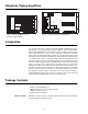
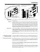
Telephone Paging Amplifiers POWER PEAK LEVEL AUDIO ENHANCEMENT TREBLE BASS VOX SENS RINGER VOLUME MUSIC MUTE MUSIC VOLUME MIC VOLUME MODEL TPU-100B 100 WATT AMPLIFIER TEL VOLUME ALC BOGEN Figure 1: TPU35B, TPU60B, TPU100B Telephone Paging Amplifier Figure 1a: TPU250 Telephone Paging Amplifier Introduction This document describes the Bogen TPU35B, TPU60B, TPU100B (See Fig.1) and TPU250 (see Fig.1A) Telephone Paging Amplifiers.
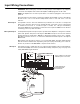
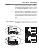
Installation Figure 3: Rack Mounting the TPU250. See NOTE below for information on alternate orientation. Figure 2: Wall Mounting the Amplifier Screw #8 x 5/8” (M4 x 16mm) with Screw #8 x 5/8 “ (M4 x 16 mm) with Synthetic washer 1/8” x 5/16” (3 x 8mm) TYP 4 PCS. Both items1/8” arexsupplied. Synthetic washer 5/16” (3 x 8 mm) TYP 4 PCS Rack Mounting Screws are not supplied.
Input Wiring Connections IMPORTANT: Before making any connections or wiring changes to the amplifier or any equipment connected to the amplifier, make sure that the amplifier is NOT plugged into an AC outlet. NOTE: The amplifier does not have a power switch, so it must be unplugged in order to turn the power off. All signal input and control wiring is made to the terminal strip and RCA connectors beneath the left side access cover.
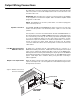
Input Wiring Connections Night Ringer Connection Either a standard telephone (analog) ring signal (90 – 105V AC, 20 – 30 Hz) or an external contact closure activates the night ringer function of the amplifier. To activate the night ringer using standard telephone (analog) ring, connect the analog station's tip lead to the TEL RING "T" terminal and connect the ring lead to the "R" terminal. If using an external contact closure, connect the closure pair across the CONTACT RING and GND terminals.
Output Wiring Connections All output wiring connections are made to the terminal strip located under the right side access panel. Loosen the two Phillips-head screws on each side of the cover and remove the cover. IMPORTANT: Before making any connections or wiring changes to the amplifier or any equipment connected to the amplifier, make sure that the amplifier is NOT plugged into an AC outlet. NOTE: The amplifier does not have a power switch, so it must be unplugged in order to turn the power off.
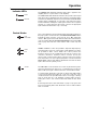
Operation Indicator LEDs POWER PEAK LEVEL Control Knobs AUDIO ENHANCEMENT TREBLE BASS VOX SENS The POWER LED illuminates whenever AC power is applied to the amplifier (there is no power switch on the amplifier). The PEAK LEVEL LED illuminates whenever the speaker output signal level approaches its maximum level. This indicator is used when setting volume levels. Maximum output level is achieved when the PEAK LEVEL indicator flashes intermittently on loud peaks of the input signal.
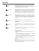
Operation RINGER VOLUME MUSIC MUTE MUSIC VOLUME MIC VOLUME RINGER VOLUME adjusts the level of the night ringer tone output. The music volume level should first be set to the customer's satisfaction. When adjusting this level, the PEAK LEVEL indicator should be used to ensure that the amplifier signal is not distorted. MUSIC MUTE adjusts the level of the background music heard during a paging announcement. The fully counterclockwise position provides maximum muting (no background music).
Specifications Technical Specifications Power Output: Frequency Response: Distortion: Hum & Noise: TPU35B: 35W RMS; TPU60B: 60W RMS; TPU100B: 100W RMS; TPU250: 250W RMS 70 Hz to 15k Hz ±1 dB Less than 1% (20 Hz to 20 kHz) MUSIC: -70 dB; TEL: -70 dB; MIC: -55 dB Sensitivity: MUSIC: 85mV; TEL: -20 dBm (77mV); MIC: 600μV Tone Control: Regulation: BASS: ±9 dB @ 100 Hz; TREBLE: ±9 dB @ 10 kHz 2 dB Inputs: Outputs: TEL: 600-ohm balanced line, transformer-isolated MUSIC: Hi-Z source, RCA jacks or screw ter
Limited Warranty; Exclusion of Certain Damages Bogen TPU-Series Telephone Paging Amplifiers (TPU35B, TPU60B, TPU100B, and TPU250) are warranted to be free from defects in material and workmanship for two (2) years from the date of sale to the original purchaser.