PagePac ® by ISSUE 2 PagePac Plus AmpliCenter V-5328020/V-5328100/V-5328300 Installation and Use 947169
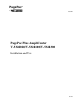
Installation Steps Note: If installed next to other equipment, including the PagePac Plus Controller and Zone Expansion Units, leave at least four inches space above and below for proper ventilation. 1. Mount the PagePac® Plus AmpliCenter to either the wall (Figure 1), cabinet, or a 19 inch rack (Figure 2). SIDE VIEW 105 - 120 VAC 210 - 240 VAC 50 - 60 Hz Figure 1. Wall Mounted Hardware FRONT DETAIL 1.
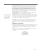
2. Connect music input wires to Left, Right, and Ground terminals, if stereo, or Left and Ground, if not (see Figure 3). Note: The optional audio background music source can be a CD or tape player, AM, FM, or commercial radio, or other audio device. Figure 3. Music Input Connections on AmpliCenter 3. Hookup speaker cable to AmpliCenter (see Figure 4). Note: If more than one speaker cable is routed to the AmpliCenter, a connector block is necessary. Refer to sample wiring diagrams on page 8.
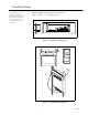
A M P L IC E N T E R P A G E M U S IC IN D N G 1 C G NI R PI T D O U T P U T D M IC G S W IT C H P A G E IN P U T L With a microphone, hook the mic switch to C1 and Grd, and the mic output to Tip and Ring. M IC O O O R Y R Y R Use Tip and Ring if connecting to a Loop Start or Ground Start interface port in host telephone system.
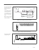
Note: If no page is heard, refer to the troubleshooting Guidelines. 8. Adjust sound levels using AmpliCenter controls, if necessary. Using a small standard screwdriver, make the following adjustments (see Figure 8). Figure 8. Test Page Adjustments 1. Adjust the Low Frequency Cut Off control. This control cuts out the low frequency bass so that horns and small speakers are not over-driven and distorted by excessive bass energy.
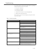
Troubleshooting Some common problems encountered when the paging system is not operating are described below. Check each item in the order listed. 1. No AC power to AmpliCenter. 2. Host telephone system failure. 3. Host system page port failure. 4. A hardwire disconnect between host system and PagePac® Plus. 5. AmpliCenter switch settings tampered with. If the problem has not been resolved by checking the preceding items, follow the steps described in Table 1. Table 1.
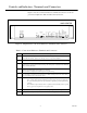
Controls and Indicators, Terminals and Connectors Figure 9 shows the controls and indicators, terminals and connectors on the rear panel of the AmpliCenter. Table 2 identifies them by function.
Connecting Speakers 1. Locate and mount all speakers in accordance with the floor plan drawing for this installation. 2. Connect each speaker to the appropriate home run or speaker-to-speaker wiring scheme as shown on the wiring plan (see Figure 10). 3. Test speaker wiring for short circuits. Measure the resistance of each home run wire run with an ohmmeter. Any pair indicating a value of less than 15 ohms must be rechecked for possible shorted wiring or speakers. Correct any problems and retest.
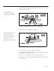
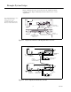
Example System Setups Figure 11 illustrates the interconnection between the AmpliCenter and the Controller, if used. Figure 12 illustrates the interconnection of two or more AmpliCenters. A M P L IC E N T E R 105 - 120 VAC 210 - 2 40 VAC 50 - 60 Hz P A G E IN S E T M O D E S W IT C H T O D R Y L O O P 6 0 0 O H M P O W E R a n d 7 0 V A U D IO T O C O N T R O L L E R F R O M A M P T O Z .E .U . R S -2 3 2 T O P C (O P T IO N A L ) 0 d B u 0 d B m N .B .
The Dry Loop 600 Ohm is a four wire interface consisting of a dry audio pair with a 600 Ohm impedance and a control pair. The page input is activated when the control pair receives a contact closure from the host equipment, connecting Cl to ground. The Dry Loop page input can also be activated by the presence of page input audio signals that exceed a set threshold. This threshold is set by the page VOX adjustment; clockwise rotation lowers the threshold and makes R more sensitive.
Specifications Table 4 describes the specifications of the AmpliCenter D20, D100, and D300 models. Table 3. AmpliCenter Specifications Features ■ Telephone Paging Access: The AmpliCenter accepts inputs from telephone system (PBX) ground start or loop start trunk ports, dry loop 600 ohm page ports, dry loop (hi Z), or amplified microphones. ■ Music interface: The AmpliCenter is the unit to which the background music source (CD, radio, tape player) is connected, for distribution to the paging system.