
Specifications


3 947923
INSTALLATION
Precautions
All precautions have been taken at the factory to
insure that the equipment functions properly when
installed correctly. Please follow the precautions
listed below before applying power to the equipment
or the equipment may be damaged and the warranty
voided.
a) If power was previously connected,
disconnect or remove power before inserting
or removing unit from the amphenol
connector.
b) Exercise caution when crossconnecting
wires that two adjacent terminals are not
bridged together.
c) Double check all connections before
applying power.
d) Use twisted pair wire for all connections.
Mounting
The Valcom V-9923B code call unit may be mounted
in a key cabinet relay rack or on the wall near the
distribution frame. When choosing a location, it is
necessary that the loop resistance of the PABX or key
system are not exceeded.
Mount the unit in a vacant space in an equipment
cabinet, rack, or key system cabinet, allowing enough
room at the rear of the unit to plug in an amphenol
connector. Mount a 66B type punchdown block near
the unit and label it per Figure 3.
Run a 25 pair cable with a female connector from the
unit to the connecting block. The cable should be
terminated on the connecting block in standard color
code order on a row of the connecting block. Verify
all connections before plugging the amphenol end of
the cable into the V-9923B code call unit.
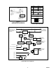
Connections to PABX
The connections required to connect the V-9923B
to a PABX are shown in Figure 4. The V-9923B
requires a loop start trunk port from the PABX for
access. If more than one link of code call is being
provided, the second V-9923B would require a trunk
also and the two trunks should be in a hunt group
within the PABX. This arrangement allows access to
the second V-9923B if the first V-9923B is in use.
NOTE: ADVISE PERSONNEL USING CODE
CALL UNIT TO ALWAYS WAIT FOR DIAL
TONE FROM CODE CALL UNIT BEFORE
DIALING IN CODE NUMBER!
To answer the code call requires a station from the
PABX. If two code call units are being used, two
stations would be required and they would have to be
in a rotary hunt group also.
Connections to Key Systems
The connections required to connect the V-9923B
to a 1A2 key system are shown in Figure 5. The T,
R, A and L leads are multiplied to all phones in the
system. Use a spare pick-up button and install a 10K
Ohm 1/4 watt 5% resistor either in the phone or at the
connecting block in series with the A lead from each
phone. The V-9923B will discontinue the code call
paging when it recognizes two phones off hook with
two 10K Ohm resistors to ground on the A leads.
NOTE: WHEN USING 1A2 KEY TELEPHONES,
THE TO AND RO LEADS THAT WERE USED
FOR PABX CONNECTION ARE NOT USED.
A
CCESS
PORT
A
NSWER
PORT
V
-9923B
CODE CALL
TO
RO
TT
RT
IN
OUT
T
R
X
ANALOG
PBX
STATION
CIRCUIT
TONE OUTPUT
TO PAGING
SYSTEM
SWITCHED
RELAY
OUTPUT
EP1
EP2AB AG BB BG LS
Y
TO –24 Vdc AND
10 Vac POWER
SUPPLIES
TO NEXT V-9923B
CODE CALL UNIT
IF EQUIPPED
INH
L
Y
X
Y
Y
PBX
OUTGOING LOOP
START CO TRUNK
10K
SPARE LINE BUTTON
ON KEY TELEPHONE
USED WITH PBX
USED WITH 1A2 KEY SYSTEM
FIGURE 2