
Specifications
2
SYSTEM DESIGN
Configuration
There are two basic ways the V-9939B
Microphone Adapter may be used:
1. It may be used with a V-1094A and
Valcom one-way amplified speaker
assemblies as a stand alone paging
system.
When using the V-9939B for access to a stand
alone paging system, the following will be
required:
• 1 V-9939B Microphone Adapter
• 1-Microphone (push to talk)
• 1 V-1094A Booster Control
• Valcom one-way amplified speaker
assemblies (type determined by job
requirements)
• Power Supply (type determined by style and
quantity of speakers - Consult the Valcom
One-Way Paging VSP for more information)
2. By using the V-9939B with a V-2001A
One Zone Page Control you may
automatically disconnect the speakers of
one zone from a multi-zone page
adapter and allow microphone access to
that zone. These configurations will
allow the microphone to override the
telephone access.
NOTE: These will work only on a zone of
ONE-WAY paging.
When using the V-9939B to override an existing
zone of telephone accessed one-way paging, the
following will be required:
• 1 V-9939B Microphone Adapter
• 1-Microphone (push to talk)
• 1 V-2001A One Zone Page Control
OR
• An existing Valcom one-way page system
Other configurations are possible. Contact
Technical Support (540) 563-2000 with
questions on specific applications.
Microphone Requirements
A standard high impedance (50,000 Ohms) or
low impedance balanced (600 Ohms)
microphone may be used. The microphone will
be required to provide a dry contact closure
(push to talk) for page access.
See Figure 3 for connections to Valcom
V-400/450 or V-420 Microphones.
INSTALLATION
These instructions cover the installation
procedures for the Valcom V-9939B and any
associated Valcom equipment. Please consult
practices for other manufacturer's equipment if
any other equipment is being used. Refer to
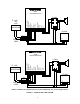
Figure 2 for location of connector connections
and designations.
The following sections contain step-by-step
instructions for wiring the V-9939B and
associated Valcom equipment. Place a check
on the appropriate line as the instruction is
completed. The instructions also include tests
along the way to verify connections have been
made correctly. If these steps are followed
exactly, installation of your Valcom system will
go smoothly and quickly. If the results of a test
do not correspond with what is shown, DO NOT
PROCEED UNTIL THE PROBLEM HAS BEEN
CORRECTED.
NOTE: During initial system setup it is
recommended that all volume controls be set
1/2 turn clockwise.
Mounting
• Using two #6 ¾ inch wood screws, mount
the unit in a convenient location near the
microphone location
NOTE: DO NOT locate the V-9939B closer
than 18 inches to a power supply or any
equipment that generates electrical noise.
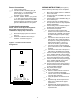
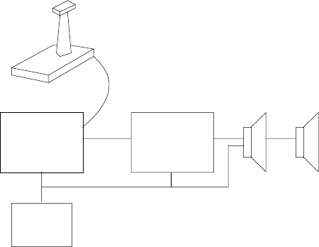
V-9939B V-1094A
Amplified Speaker
s
Power
Supply
FIGURE 1 – BLOCK DIAGRAM OF A TYPICAL INSTALLATION